Page 4 of 3342
![SUBARU LEGACY 1997 Service Repair Manual 4-4
LM13-1]
BRAKES
13
.
Anti-lock
Brake
System
(ABS)
[5
.3i
Type]
13
.
Anti-lock
Brake
System
(ABS)
[5
.3i
Type]
1
.
FEATURE
*
This
ABS
5
.3i
type
incorporates
the
hydraulic
control
unit,
ABS
contr](/manual-img/17/57434/w960_57434-3.png "SUBARU LEGACY 1997 Service Repair Manual 4-4
LM13-1]
BRAKES
13
.
Anti-lock
Brake
System
(ABS)
[5
.3i
Type]
13
.
Anti-lock
Brake
System
(ABS)
[5
.3i
Type]
1
.
FEATURE
*
This
ABS
5
.3i
type
incorporates
the
hydraulic
control
unit,
ABS
contr")
4-4
LM13-1]
BRAKES
13
.
Anti-lock
Brake
System
(ABS)
[5
.3i
Type]
13
.
Anti-lock
Brake
System
(ABS)
[5
.3i
Type]
1
.
FEATURE
*
This
ABS
5
.3i
type
incorporates
the
hydraulic
control
unit,
ABS
control
module,
valve
relay
and
motor
relay
in
one
unit
for
betterproductivity
and
lightweight
.
*
The
ABS
(Anti-lock
brake
system)
electrically
controls
brake
fluid
pressure
to
prevent
wheel
"lock"
during
braking
on
slippery
road
surfaces,
thereby
improving
directional/steering
stability
as
well
as
shortening
the
braking
distance
.
*
If
the
ABS
becomes
inoperative,
the
fail-safe
system
activates
to
ensure
it
acts
asa
conventional
brake
system
.
The
warning
light
also
comes
on
to
indicate
that
the
ABS
is
malfunctioning
.
"
The
front-and-rear
wheels
utilize
a
4-sensor,
4-channel
control
design
:
the
front
wheels
havean
independent
control
design*1
and
the
rear
wheels
have
a
select
low
control
design*2
.
*1
:
A
system
which
independently
controls
fluid
pressure
to
left
and
right
front
wheels
.
*2
:
A
system
which
provides
the
same
fluid
pressure
control
for
the
two
rear
wheels
if
either
wheel
starts
to"lock
."
10
ABS
control
moduleand
hydraulic
control
unit
(ABSCM&H/U)
Proportioning
valve
OO
Diagnosisconnector
OO
ABS
warning
light
OO
Data
link
connector
(for
SUBARU
select
monitor)
OO
Transmission
control
module
(only
AT
vehicle)
Tone
wheel
OO
ABS
sensor
09
Wheel
cylinder
O
G
sensor
(only
AWD
vehicle)
>>
Brake
switch
D
Master
cylinder
?15A
2
Page 5 of 3342
![SUBARU LEGACY 1997 Service Repair Manual
BRAKES
IM13-21
4-4
13
.
Anti-lock
Brake
System
(ABS)
[5
.3i
Type]
2
.
FUNCTIONS
OF
SENSORS
AND
ACTUATORS
Name
Function
ABS
control
moduleand
hydraulic
ABSCM-
e
Calculates
and
determine
the
conditi](/manual-img/17/57434/w960_57434-4.png "SUBARU LEGACY 1997 Service Repair Manual
BRAKES
IM13-21
4-4
13
.
Anti-lock
Brake
System
(ABS)
[5
.3i
Type]
2
.
FUNCTIONS
OF
SENSORS
AND
ACTUATORS
Name
Function
ABS
control
moduleand
hydraulic
ABSCM-
e
Calculates
and
determine
the
conditi")
BRAKES
IM13-21
4-4
13
.
Anti-lock
Brake
System
(ABS)
[5
.3i
Type]
2
.
FUNCTIONS
OF
SENSORS
AND
ACTUATORS
Name
Function
ABS
control
moduleand
hydraulic
ABSCM-
e
Calculates
and
determine
the
conditionsof
the
wheels
and
body
from
control
unit
(ABSCM&H/U)
section
the
wheel
speedsand
makes
a
proper
decision
suitable
for
the
current
situation
to
control
the
hydraulic
unit
.
In
the
ABS
operation
mode,
the
module
outputs
a
cooperative
control
signal
to
the
AT
control
module
.
(AT
vehicles
only)
Whenever
the
ignition
switch
is
placed
at
ON,
the
module
makes
a
self
diagnosis
.
When
anything
wrong
is
detected,
the
module
cuts
off
the
system
.
Communicates
with
the
Subaru
select
monitor
.
H/U-section
In
the
ABS
operation
mode,
the
H/U
changes
fluid
passages
to
control
the
fluid
pressure
of
the
wheel
cylinders
in
response
to
an
instruction
from
the
ABSCM
.
The
H/U
also
constitutes
thebrake
fluid
passage
from
the
master
cylin-
der
to
the
wheel
cylinders
together
with
pipings
.
Valve
relay-
Serves
asa
power
switch
for
the
solenoid
valve
and
motor
relay
coil
in
section
response
to
an
instruction
from
the
ABSCM
.
Motor
relay-
Serves
as
a
power
switch
for
the
pump
motor
in
response
to
an
instruc-
section
tion
from
the
ABSCM
.
Wheel
speed
sensor
(ABS
sensor)
Detects
the
wheel
speed
in
terms
of
a
change
in
the
magnetic
flux
den-
sity
passingthrough
the
sensor,
converts
it
into
an
electrical
signal,
and
outputs
the
electrical
signal
to
the
ABSCM
.
Tone
wheel
Gives
a
change
in
the
magnetic
flux
density
by
the
teeth
around
the
tone
wheel
to
let
the
ABS
sensor
generate
an
electrical
signal
.
G
sensor
(AWD
vehicle
only)
Detects
a
change
in
G
in
the
longitudinal
direction
of
the
vehicle
and
outputs
it
to
the
ABSCM
in
terms
of
a
change
in
voltage
.
Stop
light
switch
Transmits
the
information
on
whether
the
brakepedal
is
depressed
or
not
to
the
ABSCM
for
use
as
a
condition
in
determining
ABS
operation
.
ABS
warning
light
Alerts
the
driver
to
an
ABS
fault
.
When
the
diagnosis
connector
and
diagnosis
terminal
are
connected,
the
light
flashes
to
indicate
a
trouble
codes
in
response
to
an
instruction
from
the
ABSCM
.
AT
control
module
(TCM)
(AT
vehicles
only)
Provides
shift
controls
(fixing
the
speed
at
3rd
or
changing
front
and
rear
wheel
transmission
characteristics
on
4WD
vehicle)
in
response
to
an
instruction
fromthe
ABSCM
.
Page 23 of 3342
4-4
[w2sBO]
SERVICE
PROCEDURE
25
.
ABS
Control
Module
and
Hydraulic
Control
Unit
(ABSCM&H/U)
[ABS
5
.3i
Type]
B
:
INSPECTION
i
Mark
>
ABSCM&H/U
B4M
1248A
/Pressure
ga
u
ge
\
'
/\
B4M0633A
1)
Check
connected
and
fixed
condition
of
connector
.
2)
Check
specifications
of
the
mark
with
ABSCM&H/U
.
Mark
Model
C3
AWD
AT
C4
AWD
MT
C
:
CHECKING
THE
HYDRAULIC
UNIT
ABS
OPERATION
1
.
CHECKINGTHE
HYDRAULIC
UNIT
ABS
OPERATION
BY
PRESSURE
GAUGE
1)
Lift-up
vehicle
and
remove
wheels
.
2)
Disconnect
the
air
bleeder
screwsfrom
the
FL
andFR
caliper
bodies
.
3)
Connect
two
pressure
gauges
to
the
FL
andFR
cali-
perbodies
.
CAUTION
:
Pressure
gauges
used
exclusively
for
brake
fluid
must
be
used
.
e
Do
not
employ
pressure
gauge
previously
used
for
transmission
since
the
piston
seal
is
expanded
which
may
lead
to
malfunction
of
the
brake
.
NOTE
:
Wrap
sealing
tape
around
the
pressure
gauge
.
8
Page 575 of 3342
5) After remounting engine and transmission on body;
6) Bleed air from oil line with the help of a co-worker.
G2M0242
4. Clutch Disc and Cover
A: REMOVAL
1) Install ST on flywheel.
ST 498497100 CRANKSHAFT STOPPER
2) Remove clutch cover and clutch disc.
CAUTION:
�Take care not to allow oil on the clutch disc facing.
�Do not disassemble either clutch cover or clutch
disc.
G2M0243
3) Remove flywheel.
B2M0328
B: INSPECTION
1. CLUTCH DISC
1) Facing wear
Measure the depth of rivet head from the surface of facing.
Replace if facings are worn locally or worn down to less
than the specified value.
Depth of rivet head:
Standard value
1.3—1.9 mm (0.051—0.075 in)
Limit of sinking
0.3 mm (0.012 in)
CAUTION:
Do not wash clutch disc with any cleaning fluid.
12
2-10SERVICE PROCEDURE
3. Release Bearing and Lever - 4. Clutch Disc and Cover
Page 576 of 3342
5) After remounting engine and transmission on body;
6) Bleed air from oil line with the help of a co-worker.
G2M0242
4. Clutch Disc and Cover
A: REMOVAL
1) Install ST on flywheel.
ST 498497100 CRANKSHAFT STOPPER
2) Remove clutch cover and clutch disc.
CAUTION:
�Take care not to allow oil on the clutch disc facing.
�Do not disassemble either clutch cover or clutch
disc.
G2M0243
3) Remove flywheel.
B2M0328
B: INSPECTION
1. CLUTCH DISC
1) Facing wear
Measure the depth of rivet head from the surface of facing.
Replace if facings are worn locally or worn down to less
than the specified value.
Depth of rivet head:
Standard value
1.3—1.9 mm (0.051—0.075 in)
Limit of sinking
0.3 mm (0.012 in)
CAUTION:
Do not wash clutch disc with any cleaning fluid.
12
2-10SERVICE PROCEDURE
3. Release Bearing and Lever - 4. Clutch Disc and Cover
Page 579 of 3342
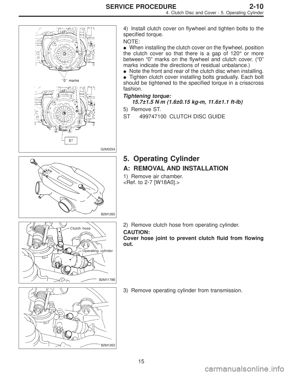
G2M0254
4) Install clutch cover on flywheel and tighten bolts to the
specified torque.
NOTE:
�When installing the clutch cover on the flywheel, position
the clutch cover so that there is a gap of 120°or more
between“0”marks on the flywheel and clutch cover. (“0”
marks indicate the directions of residual unbalance.)
�Note the front and rear of the clutch disc when installing.
�Tighten clutch cover installing bolts gradually. Each bolt
should be tightened to the specified torque in a crisscross
fashion.
Tightening torque:
15.7±1.5 N⋅m (1.6±0.15 kg-m, 11.6±1.1 ft-lb)
5) Remove ST.
ST 499747100 CLUTCH DISC GUIDE
B2M1265
5. Operating Cylinder
A: REMOVAL AND INSTALLATION
1) Remove air chamber.
B2M1179B
2) Remove clutch hose from operating cylinder.
CAUTION:
Cover hose joint to prevent clutch fluid from flowing
out.
B2M1263
3) Remove operating cylinder from transmission.
15
2-10SERVICE PROCEDURE
4. Clutch Disc and Cover - 5. Operating Cylinder
Page 580 of 3342
G2M0254
4) Install clutch cover on flywheel and tighten bolts to the
specified torque.
NOTE:
�When installing the clutch cover on the flywheel, position
the clutch cover so that there is a gap of 120°or more
between“0”marks on the flywheel and clutch cover. (“0”
marks indicate the directions of residual unbalance.)
�Note the front and rear of the clutch disc when installing.
�Tighten clutch cover installing bolts gradually. Each bolt
should be tightened to the specified torque in a crisscross
fashion.
Tightening torque:
15.7±1.5 N⋅m (1.6±0.15 kg-m, 11.6±1.1 ft-lb)
5) Remove ST.
ST 499747100 CLUTCH DISC GUIDE
B2M1265
5. Operating Cylinder
A: REMOVAL AND INSTALLATION
1) Remove air chamber.
B2M1179B
2) Remove clutch hose from operating cylinder.
CAUTION:
Cover hose joint to prevent clutch fluid from flowing
out.
B2M1263
3) Remove operating cylinder from transmission.
15
2-10SERVICE PROCEDURE
4. Clutch Disc and Cover - 5. Operating Cylinder
Page 618 of 3342
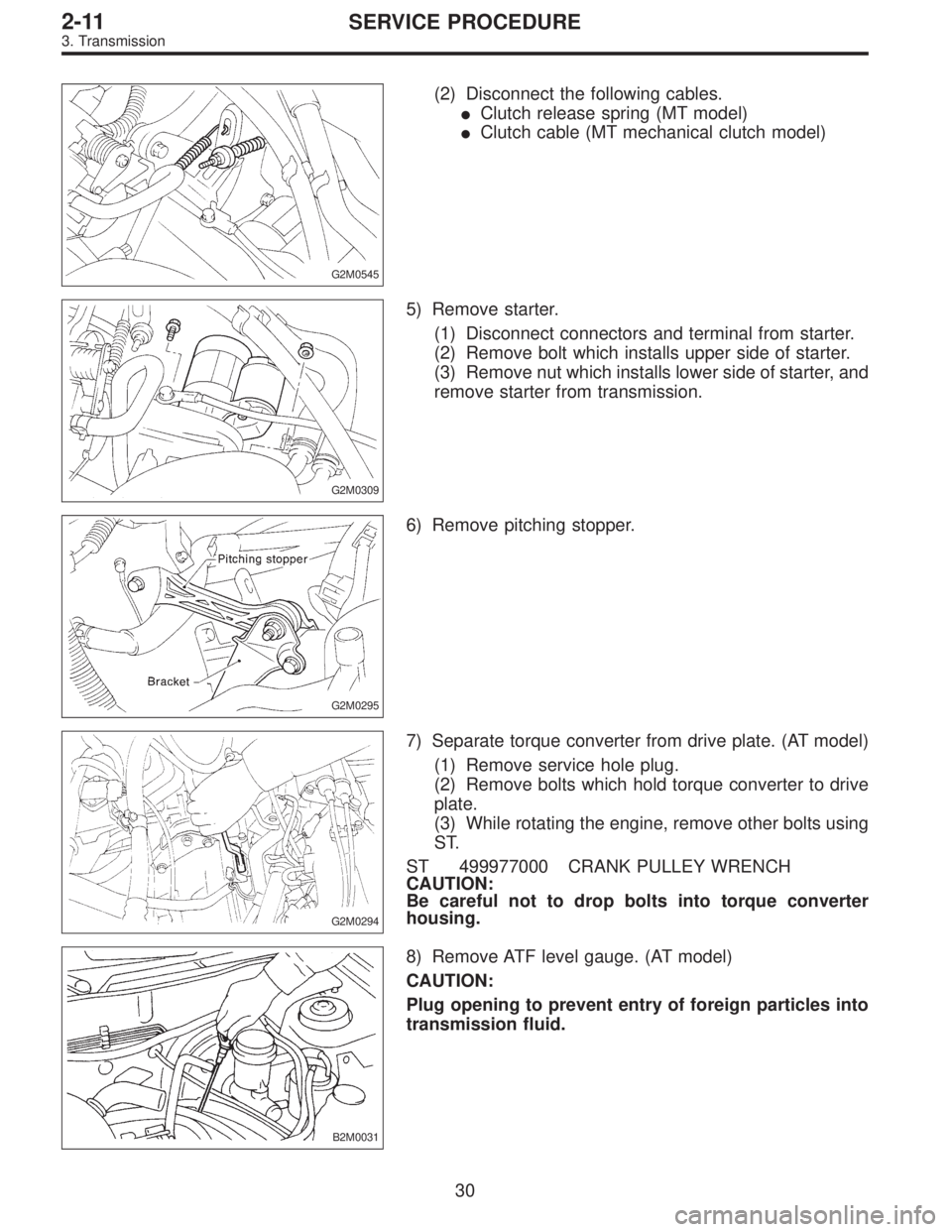
G2M0545
(2) Disconnect the following cables.
�Clutch release spring (MT model)
�Clutch cable (MT mechanical clutch model)
G2M0309
5) Remove starter.
(1) Disconnect connectors and terminal from starter.
(2) Remove bolt which installs upper side of starter.
(3) Remove nut which installs lower side of starter, and
remove starter from transmission.
G2M0295
6) Remove pitching stopper.
G2M0294
7) Separate torque converter from drive plate. (AT model)
(1) Remove service hole plug.
(2) Remove bolts which hold torque converter to drive
plate.
(3) While rotating the engine, remove other bolts using
ST.
ST 499977000 CRANK PULLEY WRENCH
CAUTION:
Be careful not to drop bolts into torque converter
housing.
B2M0031
8) Remove ATF level gauge. (AT model)
CAUTION:
Plug opening to prevent entry of foreign particles into
transmission fluid.
30
2-11SERVICE PROCEDURE
3. Transmission
![SUBARU LEGACY 1997 Service Repair Manual
4-4
[w2sBO]
SERVICE
PROCEDURE
25
.
ABS
Control
Module
and
Hydraulic
Control
Unit
(ABSCM&H/U)
[ABS
5
.3i
Type]
B
:
INSPECTION
i
Mark
>
ABSCM&H/U
B4M
1248A
/Pressure
ga
u
ge
\
/\
B4M0633A
1)
C](/manual-img/17/57434/w960_57434-22.png "SUBARU LEGACY 1997 Service Repair Manual
4-4
[w2sBO]
SERVICE
PROCEDURE
25
.
ABS
Control
Module
and
Hydraulic
Control
Unit
(ABSCM&H/U)
[ABS
5
.3i
Type]
B
:
INSPECTION
i
Mark
>
ABSCM&H/U
B4M
1248A
/Pressure
ga
u
ge
\
/\
B4M0633A
1)
C")
![SUBARU LEGACY 1997 Service Repair Manual 5) After remounting engine and transmission on body;
<Ref. to 2-11 [W3B0].>
6) Bleed air from oil line with the help of a co-worker.
<Ref. to 2-10 [W202].>
G2M0242
4. Clutch Disc and Cover
A: REMOVAL](/manual-img/17/57434/w960_57434-574.png "SUBARU LEGACY 1997 Service Repair Manual 5) After remounting engine and transmission on body;
<Ref. to 2-11 [W3B0].>
6) Bleed air from oil line with the help of a co-worker.
<Ref. to 2-10 [W202].>
G2M0242
4. Clutch Disc and Cover
A: REMOVAL")
![SUBARU LEGACY 1997 Service Repair Manual 5) After remounting engine and transmission on body;
<Ref. to 2-11 [W3B0].>
6) Bleed air from oil line with the help of a co-worker.
<Ref. to 2-10 [W202].>
G2M0242
4. Clutch Disc and Cover
A: REMOVAL](/manual-img/17/57434/w960_57434-575.png "SUBARU LEGACY 1997 Service Repair Manual 5) After remounting engine and transmission on body;
<Ref. to 2-11 [W3B0].>
6) Bleed air from oil line with the help of a co-worker.
<Ref. to 2-10 [W202].>
G2M0242
4. Clutch Disc and Cover
A: REMOVAL")