Page 40 of 3342
![SUBARU LEGACY 1997 Service Repair Manual
BRAKES
[ABS
5
.31
TYPE]
[rsao]
4-4d
6
.
Diagnostics
Chart
for
On-board
Diagnosis
System
I
TROUBLE
OCCURS
.I
Is
Select
Monitor
available?
I
Yes
1
10
.
Diagnostic
Chart
with
Select
1
Monitor
.
Ask
SUBARU LEGACY 1997 Service Repair Manual
BRAKES
[ABS
5
.31
TYPE]
[rsao]
4-4d
6
.
Diagnostics
Chart
for
On-board
Diagnosis
System
I
TROUBLE
OCCURS
.I
Is
Select
Monitor
available?
I
Yes
1
10
.
Diagnostic
Chart
with
Select
1
Monitor
.
Ask](/manual-img/17/57434/w960_57434-39.png)
BRAKES
[ABS
5
.31
TYPE]
[rsao]
4-4d
6
.
Diagnostics
Chart
for
On-board
Diagnosis
System
I
TROUBLE
OCCURS
.I
Is
Select
Monitor
available?
I
Yes
1
10
.
Diagnostic
Chart
with
Select
1
Monitor
.
Ask
the
customer
when
and
how
the
trouble
occurred
using
interview
check
list
.
6
.
Diagnostics
Chart
for
On-board
Diagnosis
System
A
:
BASIC
DIAGNOSTICS
PROCEDURE
I
PRE-INSPECTION
I
I
CALLING
UPA
TROUBLE
CODE
.
I
No
trouble
code
is
readable
.
Inspection
using
Diagnostic
Chart
for
Warning
Light
Failure
.
Record
all
trouble
codes
.
Only
the
start
code
is
issued
.
Trouble
codes
are
issued
.
Perform
diagnostics
in
accordance
with
trouble
code
.
Trouble
code
I
Repair
.
designated
.
Clear
memory
.
I
INSPECTION
MODE
I
I
CALLING
UPA
TROUBLE
CODE
.
Only
the
star
t
code
is
issued
.
CONFIRMATION
TEST
END
Inspection
using
General
Diagnostics
chart
.
B4M
1051
A
CAUTION
:
Remove
foreign
matter
(dust,
water,
etc
.)
from
the
ABSCM&H/U
connector
during
removal
and
installation
.
NOTE
:
e
To
check
harness
for
broken
wires
or
short
circuits,
shake
it
while
holding
it
or
the
connector
.
*
When
ABS
warning
light
illuminates,
read
and
record
trouble
code
indicated
by
ABS
warning
light
.
11
Page 120 of 3342
![SUBARU LEGACY 1997 Service Repair Manual
4-4d
[T1
0A01
BRAKES
[ABS
5
.3i
TYPE]
10
.
Diagnostics
Chart
with
Select
Monitor
10
.
Diagnostics
Chart
with
Select
Monitor
I
TROUBLE
OCCURS
.I
A
:
BASIC
DIAGNOSTIC
CHART
Is
Select
Monitor
avai SUBARU LEGACY 1997 Service Repair Manual
4-4d
[T1
0A01
BRAKES
[ABS
5
.3i
TYPE]
10
.
Diagnostics
Chart
with
Select
Monitor
10
.
Diagnostics
Chart
with
Select
Monitor
I
TROUBLE
OCCURS
.I
A
:
BASIC
DIAGNOSTIC
CHART
Is
Select
Monitor
avai](/manual-img/17/57434/w960_57434-119.png)
4-4d
[T1
0A01
BRAKES
[ABS
5
.3i
TYPE]
10
.
Diagnostics
Chart
with
Select
Monitor
10
.
Diagnostics
Chart
with
Select
Monitor
I
TROUBLE
OCCURS
.I
A
:
BASIC
DIAGNOSTIC
CHART
Is
Select
Monitor
available?
No
Yes
Ask
the
customer
when
and
how
the
trouble
occurred
using
interview
check
list
.
I
PRE-INSPECTION
I
Use
select
monitor,
retrieve
trouble
code
in
function
mode
FBiand
record
the
code
.
Perform
diagnostics
in
accordance
with
trouble
code
.
No
corresponding
trouble
code
Diagnostics
Chart
for
On-board
Diagnosis
System
Inspection
using
General
Diagnostics
chart
Trouble
code
is
designated
or
ABS
warning
light
constantly
remains
on
.
Repair
.
Clear
memory
.
I
INSPECTION
MODE
I
Use
select
monitor,
retrieve
trouble
code
in
function
model
FB1and
recordthe
code
.
No
trouble
code
is
designated
and
ABS
warning
light
goes
out
after
turning
on
.
I
CONFIRMATION
TEST
I
END
B4M1076A
CAUTION
:
Remove
foreign
matter
(dust,
water,
etc
.)
from
the
ABSCM&H/U
connector
during
removal
and
installation
.
NOTE
:
To
check
harness
for
broken
wires
or
short
circuits,
shake
it
while
holding
it
or
the
connector
.
102
Page 1610 of 3342

3. Rear Gate
A: REMOVAL AND INSTALLATION
CAUTION:
�Be careful not to scratch coated surfaces of vehicle
body and window glass during removal. Place a cloth
over the affected area.
�Be careful not to damage trim panels.
�Use an assistant when handling heavy parts.
�Be careful not to damage or lose small parts.
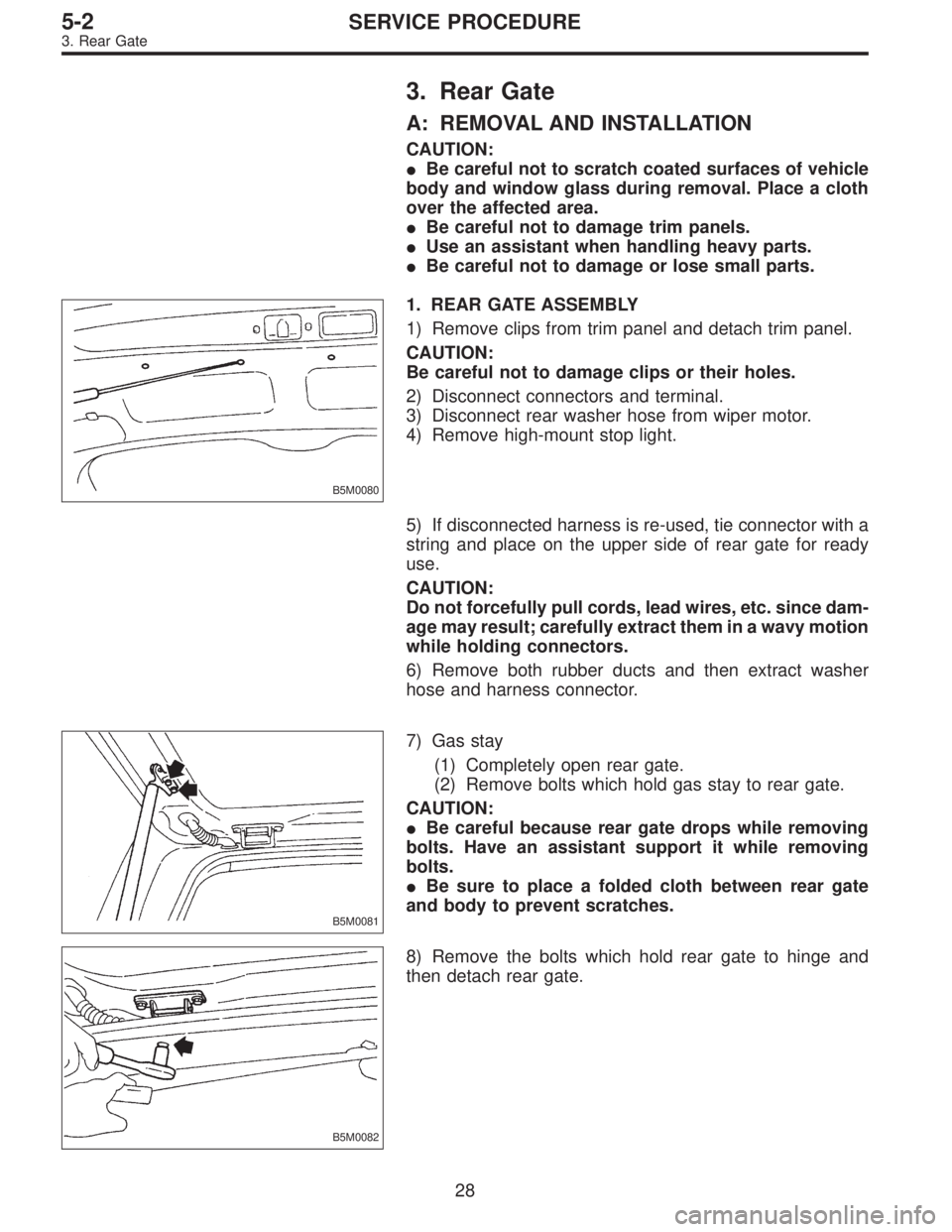
B5M0080
1. REAR GATE ASSEMBLY
1) Remove clips from trim panel and detach trim panel.
CAUTION:
Be careful not to damage clips or their holes.
2) Disconnect connectors and terminal.
3) Disconnect rear washer hose from wiper motor.
4) Remove high-mount stop light.
5) If disconnected harness is re-used, tie connector with a
string and place on the upper side of rear gate for ready
use.
CAUTION:
Do not forcefully pull cords, lead wires, etc. since dam-
age may result; carefully extract them in a wavy motion
while holding connectors.
6) Remove both rubber ducts and then extract washer
hose and harness connector.
B5M0081
7) Gas stay
(1) Completely open rear gate.
(2) Remove bolts which hold gas stay to rear gate.
CAUTION:
�Be careful because rear gate drops while removing
bolts. Have an assistant support it while removing
bolts.
�Be sure to place a folded cloth between rear gate
and body to prevent scratches.
B5M0082
8) Remove the bolts which hold rear gate to hinge and
then detach rear gate.
28
5-2SERVICE PROCEDURE
3. Rear Gate
Page 1732 of 3342

B6M0160
4. Ignition Coil
A: REMOVAL AND INSTALLATION
1. EXCEPT 2200 cc MODEL
1) Disconnect battery ground cable.
2) Disconnect connector from ignition coil.
3) Remove ignition coil.
4) Installation is in the reverse order of removal.
CAUTION:
Be sure to connect wires to their proper positions.
Failure to do so will damage unit.
B6M0772
2. 2200 cc MODEL
1) Disconnect battery ground cable.
2) Disconnect connector from ignition coil.
3) Disconnect spark plug cords from ignition coil.
4) Remove ignition coil.
5) Installation is in the reverse order of removal.
CAUTION:
Be sure to connect wires to their proper positions.
Failure to do so will damage unit.
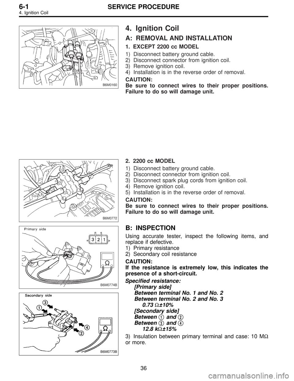
B6M0774B
B6M0773B
B: INSPECTION
Using accurate tester, inspect the following items, and
replace if defective.
1) Primary resistance
2) Secondary coil resistance
CAUTION:
If the resistance is extremely low, this indicates the
presence of a short-circuit.
Specified resistance:
[Primary side]
Between terminal No. 1 and No. 2
Between terminal No. 2 and No. 3
0.73Ω±10%
[Secondary side]
Between�
1and�2
Between�3and�4
12.8 kΩ±15%
3) Insulation between primary terminal and case: 10 MΩ
or more.
36
6-1SERVICE PROCEDURE
4. Ignition Coil
Page 1773 of 3342

B6M0119
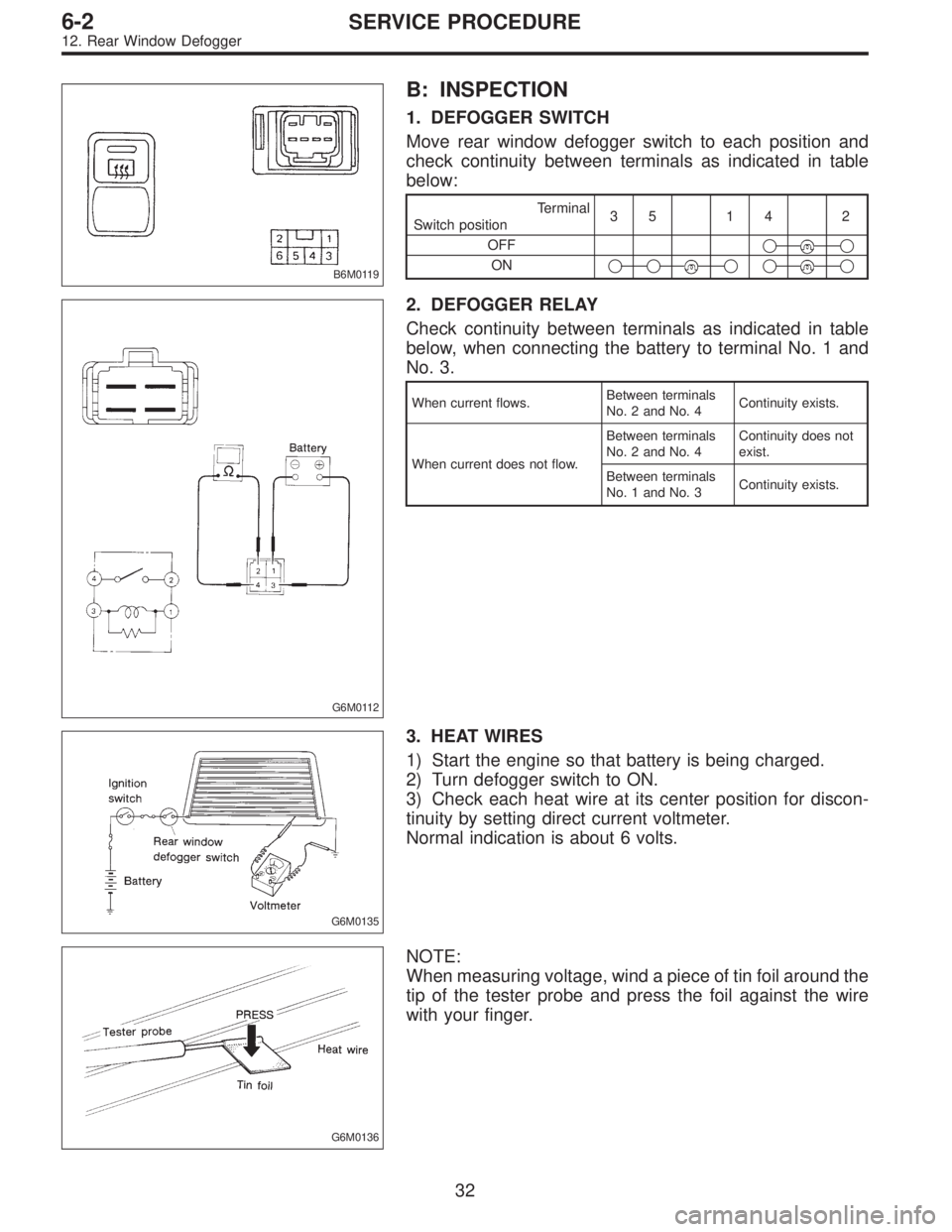
B: INSPECTION
1. DEFOGGER SWITCH
Move rear window defogger switch to each position and
check continuity between terminals as indicated in table
below:
Terminal
Switch position35 14 2
OFF�
�
ON�����
G6M0112
2. DEFOGGER RELAY
Check continuity between terminals as indicated in table
below, when connecting the battery to terminal No. 1 and
No. 3.
When current flows.Between terminals
No. 2 and No. 4Continuity exists.
When current does not flow.Between terminals
No. 2 and No. 4Continuity does not
exist.
Between terminals
No. 1 and No. 3Continuity exists.
G6M0135
3. HEAT WIRES
1) Start the engine so that battery is being charged.
2) Turn defogger switch to ON.
3) Check each heat wire at its center position for discon-
tinuity by setting direct current voltmeter.
Normal indication is about 6 volts.
G6M0136
NOTE:
When measuring voltage, wind a piece of tin foil around the
tip of the tester probe and press the foil against the wire
with your finger.
32
6-2SERVICE PROCEDURE
12. Rear Window Defogger
Page 2489 of 3342
6. Diagnostics Chart for On-board
Diagnosis System
A: BASIC DIAGNOSTICS PROCEDURE
TROUBLE OCCURS.
Ask the customer when and how the
trouble occurred using interview
check list.
PRE-INSPECTION
INSPECTION MODE
CALLING UP A TROUBLE CODE.
�No trouble code is readable.
�
Inspection using Diagnostic Chart for
Warning Light Failure.
Record all trouble codes.
Trouble codes
are issued.
�Only the start code is issued.
Inspection using General Diagnostics
Chart
Perform diagnostics in accordance with trouble code.
Trouble code
designated.
�
Repair.�
Clear memory.
INSPECTION MODE
CALLING UP A TROUBLE CODE.
Only the start code is issued.
CONFIRMATION TEST
END
NOTE:
�To check harness for broken wires or short circuits,
shake it while holding it or the connector.
�When TCS warning light illuminates, read and record
trouble code indicated by TCS warning light.
�
�
�
�
�
�
�
�
�
�
�
�
13
4-4bBRAKES
6. Diagnostics Chart for On-board Diagnosis System
Page 2521 of 3342
5. CHECK SOURCES OF SIGNAL NOISE.
1) Check that the mobile phone, personal radio and other
wireless apparatus are correctly installed.
2) Check that the antenna and other possible noise
sources are distant enough from the sensor harness.
3) Check that the sealed wires of the front harness sensor
(in the engine room) are securely grounded.
4) Check that between ABS/TCS control module and the
rear sensor harness has the correct twist pitch.
Twist pitch:
25 mm (0.98 in) or less
6. CHECK HYDRAULIC UNIT OPERATIONS.
1) Operate the ABS sequence control and check that the
brake fluid pressure at the malfunctioning brake line
increases and decreases properly.
45
4-4bBRAKES
8. Diagnostics Chart with Trouble Code
Page 2569 of 3342
10. Diagnostic Chart with Select
Monitor
A: BASIC DIAGNOSTIC CHART
TROUBLE OCCURS.
Ask the customer when and how
the trouble occurred using
interview check list.
PRE-INSPECTION
INSPECTION MODE
Use select monitor, retrieve
trouble code in function modes
FB0, FB1 and record the code.Only the start code is
designated.
�
Inspection using General
Diagnostics Chart
Trouble code designated.
Perform diagnostics in accordance with trouble code.
Trouble code
designated.
�
Repair.�
Clear memory.
INSPECTION MODE
Use select monitor, retrieve trouble code in function
modes FB0, FB1 and record the code.
No trouble code designated.
CONFIRMATION TEST
END
NOTE:
To check harness for broken wires or short circuits, shake
it while holding it or the connector.
�
�
�
�
�
�
�
�
�
�
�
93
4-4bBRAKES
10. Diagnostic Chart with Select Monitor