Page 2615 of 3342

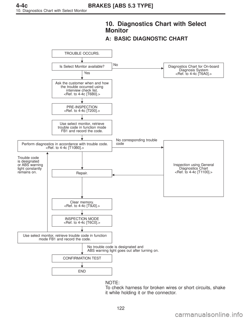
6. Diagnostics Chart for On-board
Diagnosis System
A: BASIC DIAGNOSTICS PROCEDURE
TROUBLE OCCURS.
Is Select Monitor available?
No
�Ye s
10. Diagnostic Chart with Select
Monitor
Ask the customer when and how the
trouble occurred using interview
check list.
PRE-INSPECTION
CALLING UP A TROUBLE CODE.
�No trouble code is readable.
�
Inspection using Diagnostic Chart for
Warning Light Failure.
Record all trouble codes.
Trouble codes
are issued.
�Only the start code is issued.
Inspection using General Diagnostics
Chart
Perform diagnostics in accordance with trouble code.
Trouble code
designated.
�
Repair.�
Clear memory.
INSPECTION MODE
CALLING UP A TROUBLE CODE.
Only the start code is issued.
CONFIRMATION TEST
END
NOTE:
�To check harness for broken wires or short circuits,
shake it while holding it or the connector.
�When ABS warning light illuminates, read and record
trouble code indicated by ABS warning light.
�
�
�
�
�
�
�
�
�
�
�
�
10
4-4cBRAKES [ABS 5.3 TYPE]
6. Diagnostics Chart for On-board Diagnosis System
Page 2727 of 3342
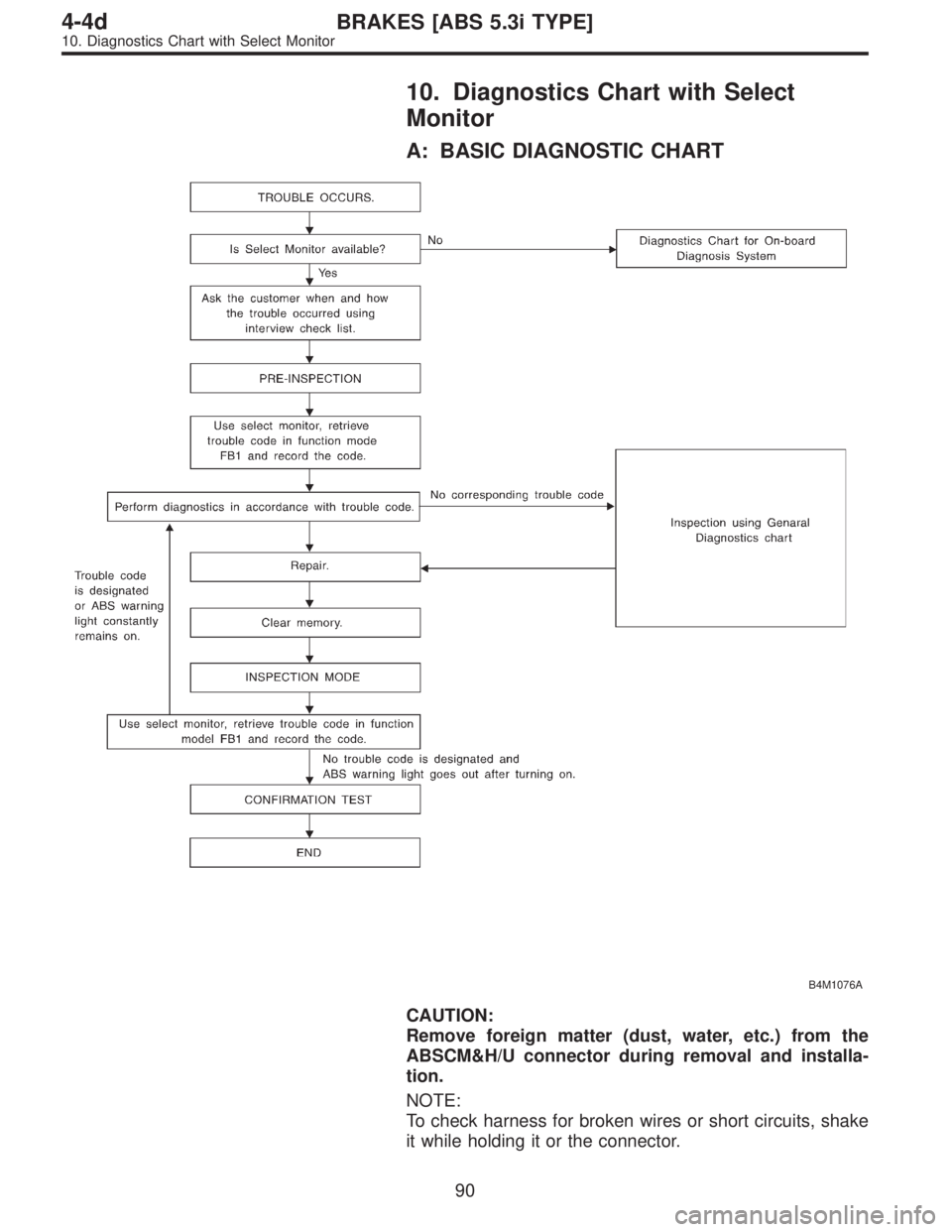
10. Diagnostics Chart with Select
Monitor
A: BASIC DIAGNOSTIC CHART
TROUBLE OCCURS.
Is Select Monitor available?
Ye s
�No
Diagnostics Chart for On-board
Diagnosis System
Ask the customer when and how
the trouble occurred using
interview check list.
PRE-INSPECTION
Use select monitor, retrieve
trouble code in function mode
FB1 and record the code.
Perform diagnostics in accordance with trouble code.
No corresponding trouble
code
�
Inspection using General
Diagnostics Chart
Trouble code
is designated
or ABS warning
light constantly
remains on.
�
Repair.�
Clear memory.
INSPECTION MODE
Use select monitor, retrieve trouble code in function
mode FB1 and record the code.
No trouble code is designated and
ABS warning light goes out after turning on.
CONFIRMATION TEST
END
NOTE:
To check harness for broken wires or short circuits, shake
it while holding it or the connector.
�
�
�
�
�
�
�
�
�
�
�
122
4-4cBRAKES [ABS 5.3 TYPE]
10. Diagnostics Chart with Select Monitor
Page 2886 of 3342
6. Diagnostics Chart for On-board
Diagnosis System
A: BASIC DIAGNOSTICS PROCEDURE
B4M1051A
CAUTION:
Remove foreign matter (dust, water, etc.) from the
ABSCM&H/U connector during removal and installa-
tion.
NOTE:
�To check harness for broken wires or short circuits,
shake it while holding it or the connector.
10
4-4dBRAKES [ABS 5.3i TYPE]
6. Diagnostics Chart for On-board Diagnosis System
Page 2966 of 3342
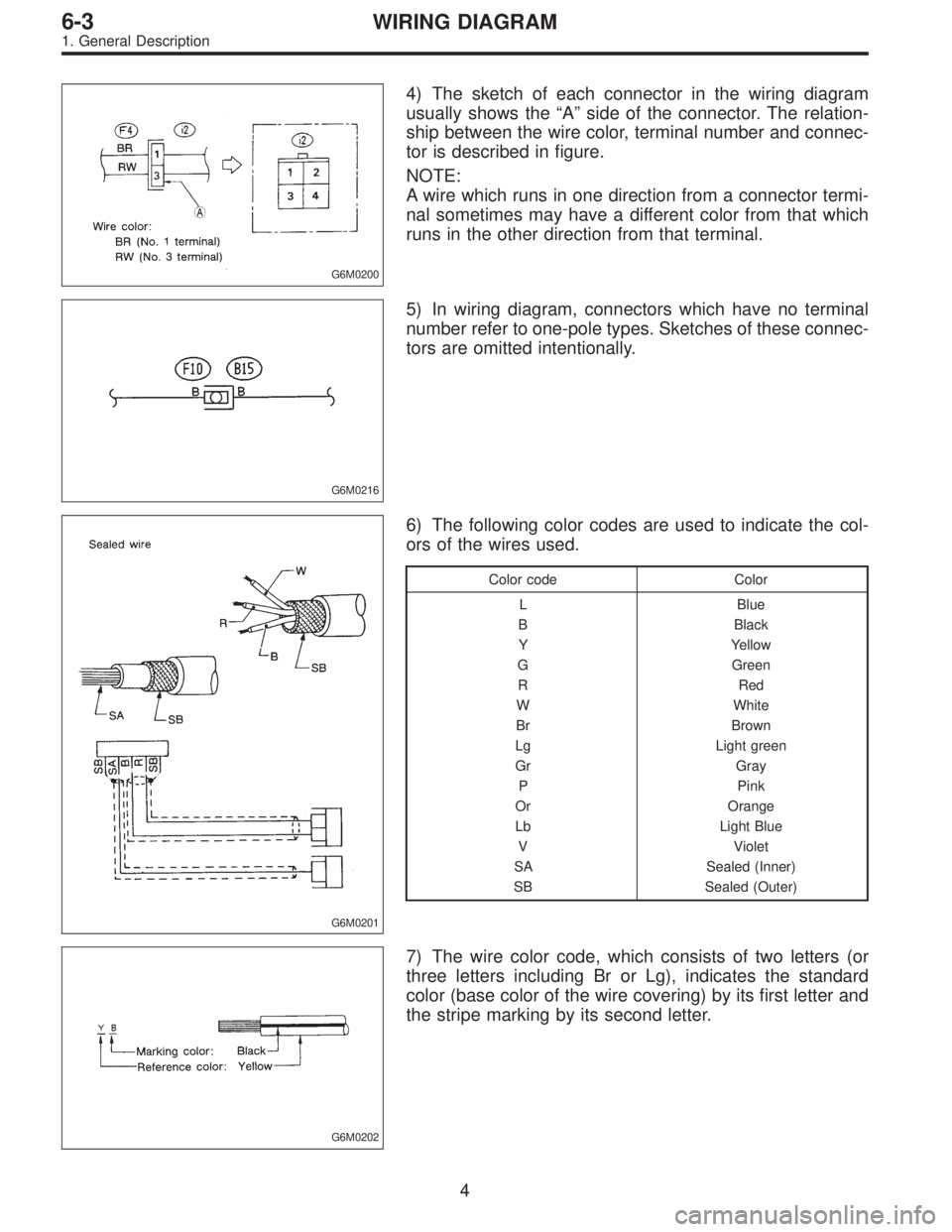
10. Diagnostics Chart with Select
Monitor
A: BASIC DIAGNOSTIC CHART
B4M1076A
CAUTION:
Remove foreign matter (dust, water, etc.) from the
ABSCM&H/U connector during removal and installa-
tion.
NOTE:
To check harness for broken wires or short circuits, shake
it while holding it or the connector.
90
4-4dBRAKES [ABS 5.3i TYPE]
10. Diagnostics Chart with Select Monitor
Page 3183 of 3342
G6M0200
4) The sketch of each connector in the wiring diagram
usually shows the“A”side of the connector. The relation-
ship between the wire color, terminal number and connec-
tor is described in figure.
NOTE:
A wire which runs in one direction from a connector termi-
nal sometimes may have a different color from that which
runs in the other direction from that terminal.
G6M0216
5) In wiring diagram, connectors which have no terminal
number refer to one-pole types. Sketches of these connec-
tors are omitted intentionally.
G6M0201
6) The following color codes are used to indicate the col-
ors of the wires used.
Color code Color
L Blue
B Black
Y Yellow
G Green
RRed
W White
Br Brown
Lg Light green
Gr Gray
P Pink
Or Orange
Lb Light Blue
V Violet
SA Sealed (Inner)
SB Sealed (Outer)
G6M0202
7) The wire color code, which consists of two letters (or
three letters including Br or Lg), indicates the standard
color (base color of the wire covering) by its first letter and
the stripe marking by its second letter.
4
6-3WIRING DIAGRAM
1. General Description
Page 3184 of 3342

8) The table below lists the nominal sectional areas and
allowable currents of the wires.
Nominal
sectional area
mm
2
No. of strands/
strand diameterOutside
diameter of
finished wiring
mmAllowable
current
Amps/40°C
0.3 7/0.26 1.8 7
0.5 7/0.32 2.2 (or 2.0) 12
0.75 30/0.18 2.6 (or 2.4) 16
0.85 11/0.32 2.4 (or 2.2) 16
1.25 16/0.32 2.7 (or 2.5) 21
2 26/0.32 3.1 (or 2.9) 28
3 41/0.32 3.8 (or 3.6) 38
5 65/0.32 4.6 (or 4.4) 51
8 50/0.45 5.5 67
CAUTION:
When replacing or repairing a wire, be sure to use the
same size and type of the wire which was originally
used.
NOTE:
�The allowable current in the above table indicates the
tolerable amperage of each wire at an ambient tempera-
ture of 40°C (104°F).
�The allowable current changes with ambient tempera-
ture. Also, it changes if a bundle of more than two wires is
used.
G6M0203
9) Each unit is directly grounded to the body or indirectly
grounds through a harness ground terminal. Different sym-
bols are used in the wiring diagram to identify the two
grounding systems.
The ground points shown in the wiring diagram refer to the
following:
�GBBody ground
�GEEngine ground
�GRRadio ground
�GDRear defogger ground
All wiring harnesses are provided with a ground point which
should be securely connected.
5
6-3WIRING DIAGRAM
1. General Description
Page 3190 of 3342
3. Working Precautions
1. PRECAUTIONS WHEN WORKING WITH THE
PARTS MOUNTED ON THE VEHICLE
1) When working under a vehicle which is jacked-up,
always be sure to use safety stands.
2) The parking brake must always be applied during work-
ing. Also, in automatic transmission vehicles, keep the
select lever set to the P (Parking) range.
3) Be sure the workshop is properly ventilated when run-
ning the engine. Further, be careful not to touch the belt or
fan while the engine is operating.
4) Be careful not to touch hot metal parts, especially the
radiator and exhaust system immediately after the engine
has been shut off.
2. PRECAUTIONS IN TROUBLE DIAGNOSIS AND
REPAIR OF ELECTRIC PARTS
1) The battery cable must be disconnected from the bat-
tery’s () terminal, and the ignition switch must be set to the
OFF position, unless otherwise required by the diagnos-
tics.
2) Securely fasten the wiring harness with clamps and
slips so that the harness does not interfere with the body
end parts or edges and bolts or screws.
3) When installing parts, be careful not to catch them on
the wiring harness.
G6M0212
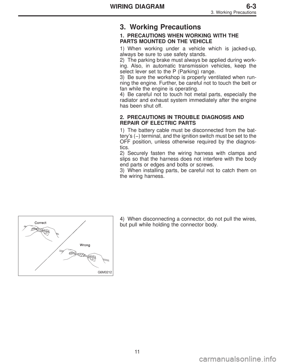
4) When disconnecting a connector, do not pull the wires,
but pull while holding the connector body.
11
6-3WIRING DIAGRAM
3. Working Precautions
Page 3193 of 3342
F: CONNECTOR SKETCH
1. Each connector sketch clearly identifies the
shape and color of a connector as well as
terminal locations. Non-colored connectors
are indicated in natural color.
2. When more than two types of connector
number are indicated in a connector sketch,
it means that the same type connectors are
used.
G: GROUND
Each grounding point can be located easily by
referring to the corresponding wiring harness.
H: DIODE
A symbol is used to indicate a diode.
I: WIRE TRACING ON EXTENDED
WIRING DIAGRAMS
For a wiring diagram extending over at least two
pages, a symbol (consisting of the same charac-
ters with arrows), as shown below, facilitates
wire tracing from one page to the next.
A)A, B)B
J: SYMBOLS OF WIRE CONNECTION
AND CROSSING
Symbol Refers to wires which are
connected and branched
at the“dot”point.
Symbol Refers to wires which are
crossed but not con-
nected.
K: POWER SUPPLY ROUTING
A symbol is used to indicate the power supply in
each wiring diagram.
“MB-5”,“MB-6”, etc., which are used as power
supply symbols throughout the text, correspond
with those shown in the POWER SUPPLY
ROUTING in the wiring diagram.
Accordingly, using the POWER SUPPLY ROUT-
ING and wiring diagrams permits service per-
sonnel to understand the entire electrical
arrangement of a system.
L: S.M.J.
A symbol is used to indicate the terminal
arrangement of the super multiple junction. The
S.M.J. is not shown in respective wiring dia-
grams but is indicated on the next page.
SYMBOLS AND ABBREVIATIONS
A number of symbols and abbreviations are used
in each wiring diagram to easily identify parts or
circuits.
14
6-3WIRING DIAGRAM
4. How to Use Wiring Diagram