Page 1616 of 3342

G5M0407
4) Positioning glass
(1) Mount glass on body.
(2) Adjust position of glass so that gap between body
and glass is uniform on all sides.
(3) Put matching pin on body and glass in several
places.
B5M0088A
5) Cleaning glass
(1) Dismount glass from body.
(2) Clean surface of glass to be adhered with alcohol
or white gasoline.
6) Stick dam rubber and install front molding upper.
While aligning ceramic print notch�
1on windshield upper
portion with mark�
2in center of upper front molding, install
upper front molding on windshield.
G5M0495
7) Application of primer
(1) Using a sponge, apply primer to part of glass to be
adhered.
(2) Apply primer to part of body to be adhered.
CAUTION:
�Primer is hard to wipe off of body paint, instrument
panel, inner trim, etc. So put masking around these
areas for protection.
�After application, let 1st primer dry spontaneously
for about 10 minutes.
�Do not touch primer-coated surface under any cir-
cumstances.
G5M0408
8) Application of adhesive
(1) Cut nozzle tip of cartridge as shown in figure.
(2) Open cartridge and put it into a gun with nozzle
attached.
(3) Apply adhesive uniformly to all sides of adhesion
surface while operating gun along glass end face.
34
5-2SERVICE PROCEDURE
5. Windshield
Page 1622 of 3342
2) Cleaning of body surface
(1) Remove chips, dirt and dust from body surface.
(2) Clean body wall surface and upper surface of adhe-
sive layer with a solvent such as alcohol or white gaso-
line.
3) Cleaning glass
(1) Remove dirt and dust from surface of glass to be
adhered.
(2) Clean surface of glass to be adhered with alcohol
or white gasoline.
G5M0495
4) Application of primer
(1) Using a sponge, apply primer to surface of glass to
be adhered.
(2) Apply primer to surface of body to be adhered.
CAUTION:
�If primer has dropped on body finish, it is hard to
wipe it off. So protect with masking.
�Primer must not project from black frame of glass.
�After applying primer, let it dry spontaneously for
about 10 minutes.
G5M0414
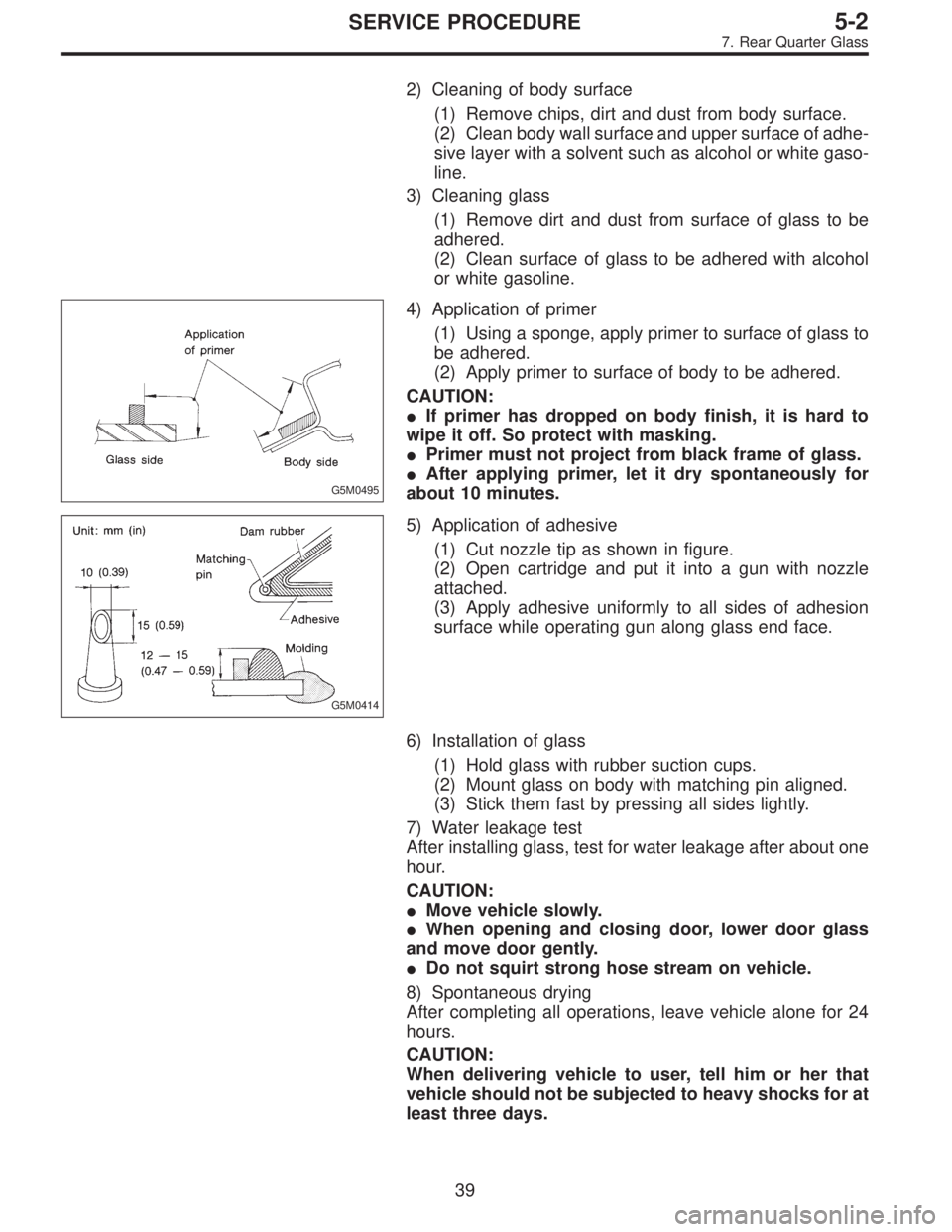
5) Application of adhesive
(1) Cut nozzle tip as shown in figure.
(2) Open cartridge and put it into a gun with nozzle
attached.
(3) Apply adhesive uniformly to all sides of adhesion
surface while operating gun along glass end face.
6) Installation of glass
(1) Hold glass with rubber suction cups.
(2) Mount glass on body with matching pin aligned.
(3) Stick them fast by pressing all sides lightly.
7) Water leakage test
After installing glass, test for water leakage after about one
hour.
CAUTION:
�Move vehicle slowly.
�When opening and closing door, lower door glass
and move door gently.
�Do not squirt strong hose stream on vehicle.
8) Spontaneous drying
After completing all operations, leave vehicle alone for 24
hours.
CAUTION:
When delivering vehicle to user, tell him or her that
vehicle should not be subjected to heavy shocks for at
least three days.
39
5-2SERVICE PROCEDURE
7. Rear Quarter Glass
Page 1765 of 3342
G6M0021
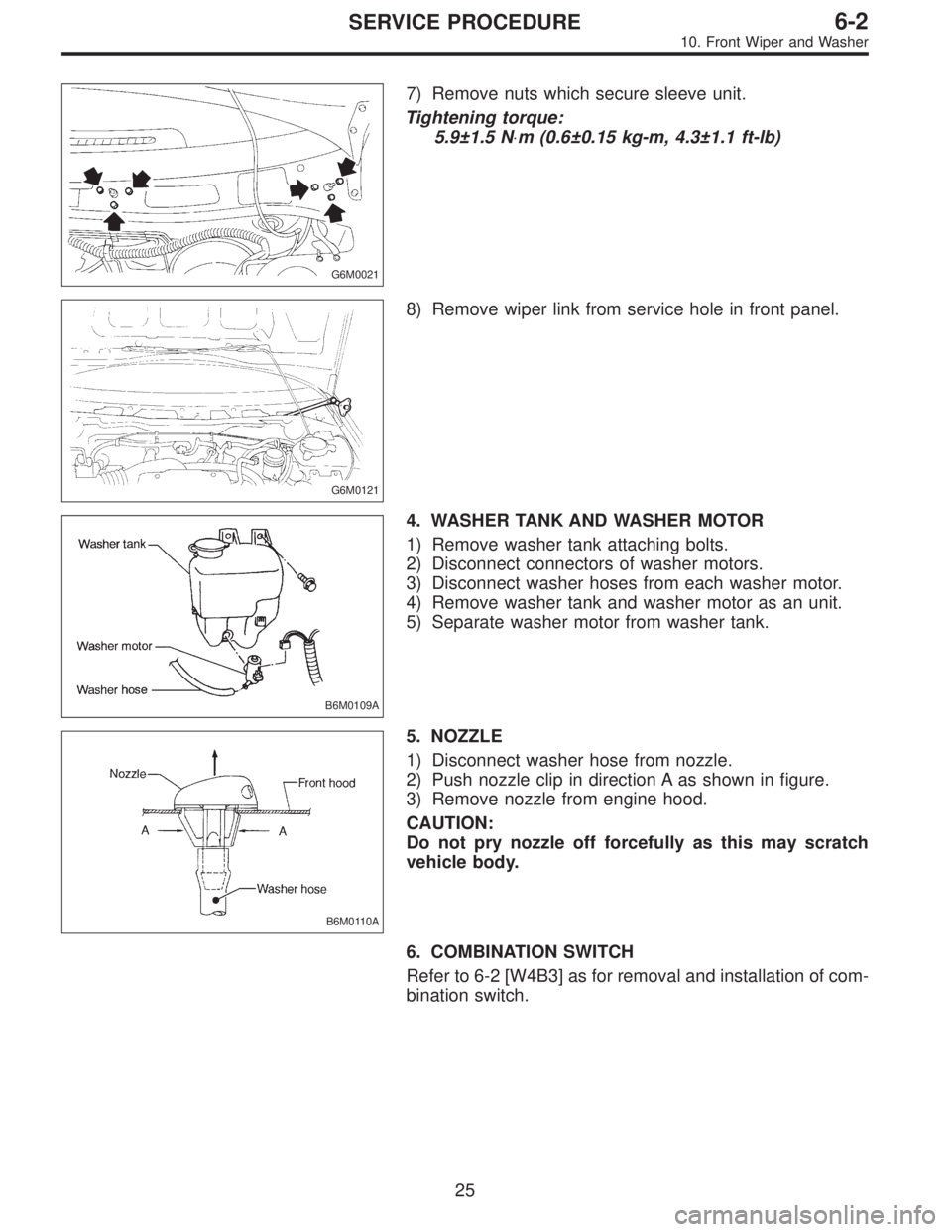
7) Remove nuts which secure sleeve unit.
Tightening torque:
5.9±1.5 N⋅m (0.6±0.15 kg-m, 4.3±1.1 ft-lb)
G6M0121
8) Remove wiper link from service hole in front panel.
B6M0109A
4. WASHER TANK AND WASHER MOTOR
1) Remove washer tank attaching bolts.
2) Disconnect connectors of washer motors.
3) Disconnect washer hoses from each washer motor.
4) Remove washer tank and washer motor as an unit.
5) Separate washer motor from washer tank.
B6M0110A
5. NOZZLE
1) Disconnect washer hose from nozzle.
2) Push nozzle clip in direction A as shown in figure.
3) Remove nozzle from engine hood.
CAUTION:
Do not pry nozzle off forcefully as this may scratch
vehicle body.
6. COMBINATION SWITCH
Refer to 6-2 [W4B3] as for removal and installation of com-
bination switch.
25
6-2SERVICE PROCEDURE
10. Front Wiper and Washer
Page 1768 of 3342
G6M0126
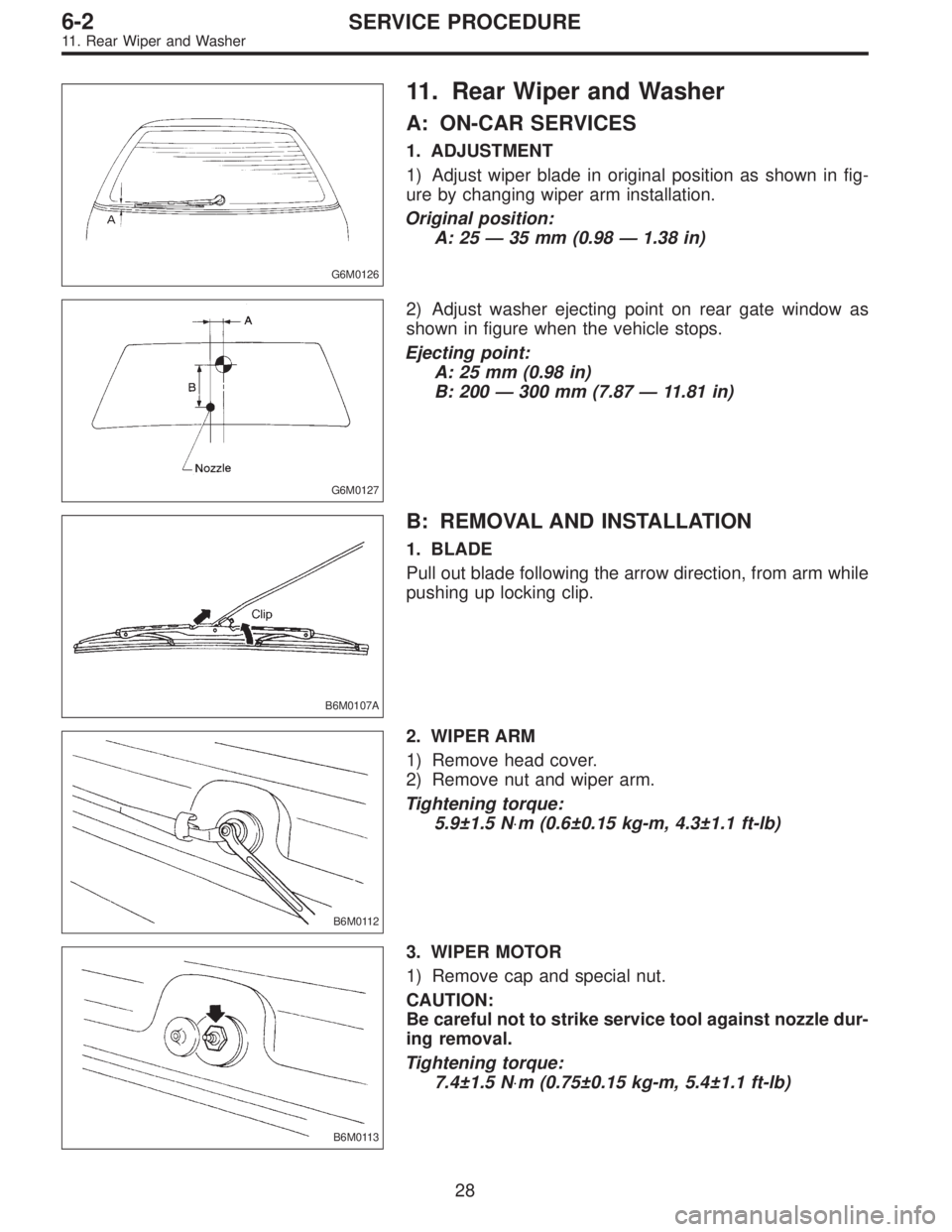
11. Rear Wiper and Washer
A: ON-CAR SERVICES
1. ADJUSTMENT
1) Adjust wiper blade in original position as shown in fig-
ure by changing wiper arm installation.
Original position:
A: 25 — 35 mm (0.98 — 1.38 in)
G6M0127
2) Adjust washer ejecting point on rear gate window as
shown in figure when the vehicle stops.
Ejecting point:
A: 25 mm (0.98 in)
B: 200 — 300 mm (7.87 — 11.81 in)
B6M0107A
B: REMOVAL AND INSTALLATION
1. BLADE
Pull out blade following the arrow direction, from arm while
pushing up locking clip.
B6M0112
2. WIPER ARM
1) Remove head cover.
2) Remove nut and wiper arm.
Tightening torque:
5.9±1.5 N⋅m (0.6±0.15 kg-m, 4.3±1.1 ft-lb)
B6M0113
3. WIPER MOTOR
1) Remove cap and special nut.
CAUTION:
Be careful not to strike service tool against nozzle dur-
ing removal.
Tightening torque:
7.4±1.5 N⋅m (0.75±0.15 kg-m, 5.4±1.1 ft-lb)
28
6-2SERVICE PROCEDURE
11. Rear Wiper and Washer