Page 1090 of 3342
 Loosen the left and right side steering tie-rods lock nuts.
2) Turn the left and right tie rods equal amounts until the
toe-in is at the specification.
Both the left and right t")
G4M0482
�Adjustment
1) Loosen the left and right side steering tie-rods lock nuts.
2) Turn the left and right tie rods equal amounts until the
toe-in is at the specification.
Both the left and right tie-rods are right-hand threaded. To
increase toe-in, turn both tie-rods clockwise equal amounts
(as viewed from the inside of the vehicle).
3) Tighten tie-rod lock nut.
Tightening torque:
83±5 N⋅m (8.5±0.5 kg-m, 61.5±3.6 ft-lb)
CAUTION:
Correct tie-rod boot, if it is twisted.
NOTE:
Check the left and right wheel steering angle is within
specifications.
M4A0059
4. REAR WHEEL TOE-IN (FWD MODEL)
�Inspection
1) Using a toe-in gauge, measure rear wheel toe-in.
Toe-in: 0±3 mm (0±0.12 in)
2) Mark rear sides of left and right tires at height corre-
sponding to center of spindles and measure distance“B”
between marks.
3) Move vehicle forward so that marks line up with front
sides at height corresponding to center of spindles.
4) Measure distance“A”between left and right marks.
Toe-in can then be obtained by the following equation:
B�A = Toe-in
G4M0483
�Adjustment
1) Remove cap from lateral link and loosen self-locking
nut.
CAUTION:
�When loosening or tightening adjusting bolt, hold
the bolt head and loosen self-locking nut.
�Replace self-locking nut with a new one.
2) Using two wrenches, turn adjusting wheel and adjusting
bolt equally in opposite directions so that toe-in is at the
specification.
11
4-1SERVICE PROCEDURE
1. On-car Services
Page 1094 of 3342
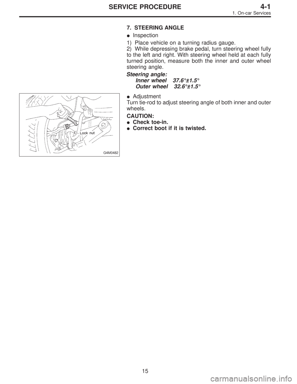
7. STEERING ANGLE
�Inspection
1) Place vehicle on a turning radius gauge.
2) While depressing brake pedal, turn steering wheel fully
to the left and right. With steering wheel held at each fully
turned position, measure both the inner and outer wheel
steering angle.
Steering angle:
Inner wheel 37.6°±1.5°
Outer wheel 32.6°±1.5°
G4M0482
�Adjustment
Turn tie-rod to adjust steering angle of both inner and outer
wheels.
CAUTION:
�Check toe-in.
�Correct boot if it is twisted.
15
4-1SERVICE PROCEDURE
1. On-car Services
Page 1208 of 3342
![SUBARU LEGACY 1997 Service Repair Manual �Make adjustment so that steering wheel can be rotated
fully from lock to lock without binding.
9) Check for service limit as per article of“Service limit”.
<Ref. to 4-3 [W3C1].> Make replacement](/manual-img/17/57434/w960_57434-1207.png "SUBARU LEGACY 1997 Service Repair Manual �Make adjustment so that steering wheel can be rotated
fully from lock to lock without binding.
9) Check for service limit as per article of“Service limit”.
<Ref. to 4-3 [W3C1].> Make replacement")
�Make adjustment so that steering wheel can be rotated
fully from lock to lock without binding.
9) Check for service limit as per article of“Service limit”.
Make replacement and adjustment
if necessary.
10) Install boot and mounting rubber to housing.
NOTE:
Apply grease through small hole in boot.
G4M0123
11) Fit clip (large) to boot, and then install boot to gearbox
while holding boot flange.
After installing boot, fold back boot flange to the extent that
large clip can not be seen.
NOTE:
�Before installing boot, be sure to apply grease to the
groove of tie-rod.
�Install fitting portions of boots to the following portions in
both sides of assembled steering gearbox.
1. The groove on gearbox
2. The groove on the rod
�Make sure that boot is installed without unusual inflation
or deflation.
G4M0124
12) Turn boot until it seats well on gearbox and rubber
mounting, then bend boot flange back.
G4M0125
13) Fix boot end with clip (small).
CAUTION:
Use screwdriver with blunted tip to prevent boot from
damage, when installing.
NOTE:
After installing, check boot end is positioned into groove on
tie-rod.
24
4-3SERVICE PROCEDURE
3. Steering Gearbox (Power Steering System) [LHD model]
Page 1211 of 3342
G4M0132
15) After adjusting toe-in and steering angle, tighten lock
nut on tie-rod end.
Tightening torque:
83±5 N⋅m (8.5±0.5 kg-m, 61.5±3.6 ft-lb)
CAUTION:
When adjusting toe-in, hold boot as shown to prevent
it from being rotated or twisted. If twisted, straighten it.
G4M0133
F: ADJUSTMENT
1) Adjust front toe.
Standard of front toe:
IN 3—OUT 3 mm (IN 0.12—OUT 0.12 in)
2) Adjust steering angle of wheels.
Inner wheel: 37.6°±1.5
Outer wheel: 32.6°±1.5
B4M0133A
3) If steering wheel spokes are not horizontal when wheels
are set in the straight ahead position, and error is more
than 5°on the periphery of steering wheel, correctly re-in-
stall the steering wheel.
G4M0135
4) If steering wheel spokes are not horizontal with vehicle
set in the straight ahead position after this adjustment,
correct it by turning the right and left tie-rods in the same
direction by the same turns.
27
4-3SERVICE PROCEDURE
3. Steering Gearbox (Power Steering System) [LHD model]
Page 1223 of 3342
2) Adjust steering angle of wheels.
Standard of steering angle:
Inner wheel 37.6°±1.5°
Outer wheel 32.6°±1.5°
B4M0133A
3) If steering wheel spokes are not horizontal when wheels
are set in the straight ahead position, and error is more
than 5°on the periphery of steering wheel, correctly re-in-
stall the steering wheel.
G4M0135
4) If steering wheel spokes are not horizontal with vehicle
set in the straight ahead position after this adjustment,
correct it by turning the right and left tie-rods in the same
direction by the same amount.
39
4-3SERVICE PROCEDURE
4. Steering Gearbox (Power Steering System) [RHD model]
Page 1224 of 3342
![SUBARU LEGACY 1997 Service Repair Manual 5. Control Valve (Power Steering
Gearbox) [LHD model]
NOTE:
This section focuses on the disassembly and reassembly
of control valve. For the inspection and adjustment and the
service procedures for as](/manual-img/17/57434/w960_57434-1223.png "SUBARU LEGACY 1997 Service Repair Manual 5. Control Valve (Power Steering
Gearbox) [LHD model]
NOTE:
This section focuses on the disassembly and reassembly
of control valve. For the inspection and adjustment and the
service procedures for as")
5. Control Valve (Power Steering
Gearbox) [LHD model]
NOTE:
This section focuses on the disassembly and reassembly
of control valve. For the inspection and adjustment and the
service procedures for associated parts, refer to“Steering
Gearbox”.
G4M0136
�1Power cylinder
�
2Cylinder
�
3Rack piston
�
4Rack axle
�
5Input shaft�
6Torsion bar
�
7Valve housing
�
8Valve body
�
9Control valve�
10Pipe B
�
11Pipe A
�
12Pinion
�
13Pinion axle
A: CHECKING OIL LEAKING POINTS
1. OIL LEAKING POINTS
1) If leak point is other than a, b, c, or d, perform check
step 5) in 4-3 [W5A2] before dismounting gearbox from
vehicle. If gearbox is dismounted without confirming where
the leak is, it must be mounted again to locate the leak
point.
2) Even if the location of the leak can be easily found by
observing the leaking condition, it is necessary to thor-
oughly remove the oil from the suspected portion and turn
the steering wheel from lock to lock about 30 to 40 times
with engine running, then make comparison of the sus-
pected portion between immediately after and several
hours after this operation.
3) Before starting oil leak repair work, be sure to clean the
gearbox, hoses, pipes, and surrounding parts. After com-
pleting repair work, clean these areas again.
40
4-3SERVICE PROCEDURE
5. Control Valve (Power Steering Gearbox) [LHD model]
Page 1233 of 3342
![SUBARU LEGACY 1997 Service Repair Manual 6. Control Valve (Power Steering
Gearbox) [RHD model]
NOTE:
This section focuses on the disassembly and reassembly
of control valve. For the inspection and adjustment and the
service procedures for as](/manual-img/17/57434/w960_57434-1232.png "SUBARU LEGACY 1997 Service Repair Manual 6. Control Valve (Power Steering
Gearbox) [RHD model]
NOTE:
This section focuses on the disassembly and reassembly
of control valve. For the inspection and adjustment and the
service procedures for as")
6. Control Valve (Power Steering
Gearbox) [RHD model]
NOTE:
This section focuses on the disassembly and reassembly
of control valve. For the inspection and adjustment and the
service procedures for associated parts, refer to“Steering
Gearbox”.
B4M0668A
A: CHECKING OIL LEAKING POINTS
1. OIL LEAKING POINTS
1) If leak point is other than a, b, c, or d, perform check
step 5) in 4-3 [W6A2] before dismounting gearbox from
vehicle. If gearbox is dismounted without confirming where
the leak is, it must be mounted again to locate the leak
point.
2) Even if the location of the leak can be easily found by
observing the leaking condition, it is necessary to thor-
oughly remove the oil from the suspected portion and turn
the steering wheel from lock to lock about 30 to 40 times
with engine running, then make comparison of the sus-
pected portion between immediately after and several
hours after this operation.
3) Before starting oil leak repair work, be sure to clean the
gearbox, hoses, pipes, and surrounding parts. After com-
pleting repair work, clean these areas again.
49
4-3SERVICE PROCEDURE
6. Control Valve (Power Steering Gearbox) [RHD model]
Page 1239 of 3342
 Apply a coat of specified steering grease to ST surface,
and install ST onto end of input shaft. Insert pinion and
valve until“A”of oil seal contacts“B”of valve housing. The
ST is u")
G4M0841
5) Apply a coat of specified steering grease to ST surface,
and install ST onto end of input shaft. Insert pinion and
valve until“A”of oil seal contacts“B”of valve housing. The
ST is used to prevent scratching Y-packing.
ST 34099FA020 GUIDE
G4M0842
6) While supporting pinion and valve, push end of pinion
until bearing contacts brazed end of valve housing.
CAUTION:
Do not allow spacer to extend beyond brazed end.
Otherwise, pinion cannot be inserted properly.
G4M0843
7) Apply a coat of grease to sealing lips of dust cover, and
insert dust cover until it contacts staged portion of input
shaft.
8) Adjust sealing lip-to-housing end clearance to 0 to 0.5
mm (0 to 0.020 in). If sealing lip is too close to housing end,
steering wheel will not return smoothly; if it is too far from
housing end, dust or dirt will enter the clearance.
NOTE:
Ensure that pinion and valve is properly positioned in valve
housing before adjustment.
G4M0826
2. PINION AND VALVE ASSEMBLY
�Removal
1) Remove snap ring securing valve sleeve to pinion and
valve, and remove valve sleeve.
CAUTION:
Be careful not to scratch pinion and valve when remov-
ing snap ring.
G4M0827
2) Remove oil seal and spacer.
3) Using a long rod, remove seal ring and O-ring from
pinion.
CAUTION:
Be careful not to scratch outer surface and seal ring
groove of input shaft. If scratched, sealing effect will
be lost, resulting in a malfunctioning valve.
55
4-3SERVICE PROCEDURE
6. Control Valve (Power Steering Gearbox) [RHD model]
 After adjusting toe-in and steering angle, tighten lock
nut on tie-rod end.
Tightening torque:
83±5 N⋅m (8.5±0.5 kg-m, 61.5±3.6 ft-lb)
CAUTION:
When adjusting toe-in, hold boot as sho")
 Adjust steering angle of wheels.
Standard of steering angle:
Inner wheel 37.6°±1.5°
Outer wheel 32.6°±1.5°
B4M0133A
3) If steering wheel spokes are not horizontal when wheels
are set in the s")