Page 3 of 3342

R18
2
Black
B-3
Rear
speaker
RH
R19
2B-3
High-mounted
s")
8
.
Electrical
Wiring
Harness
and
Ground
Point
Connector
Connecting
to
No
.
Pole
Color
Area
No
.
Name
R17
1
Black
A-3
Rear
defogger
(Power)
R18
2
Black
B-3
Rear
speaker
RH
R19
2B-3
High-mounted
stop
light
R20
2
Blue
B-2
Trunk
room
light
R21
2
Black
B-2
Rear
speaker
LH
R22
1
Brown
B-1
Rear
door
switch
LH
R23
3
B-2
Power
antenna
R24
6B-3
R60
Trunk
lid
cord(Without
security
system)
8
B-3
R60
Trunk
lid
cord
(With
security
system)
R25
2
Black
B-4
Rear
defogger
condenser
R26
4
B-4
Rear
combination
light
RH
R27
2
B-4
Trunk
room
light
switch
R28
4
B-3
Rear
combination
light
LH
R45
6
B-4
Trailer
connector
(SUS
model)
R47
3B-3Fueltank
pressure
sensor
R60
6B-4
R24
Rear
wiring
harness
(Without
security
system)
8B-4
R24
Rear
wiring
harness
(With
security
system)
R61
3B-4
Key
switch
(Security)
R62
4B-4
Rear
finisher
light
RH
R63
2B-3
License
plate
light
R64
4B-3
Rear
finisher
light
LH
R65
1
Black
A-2
Rear
defogger(Ground)
R66
2
Black
B-4
E
High-mounted
stop
light
(Rear
spoiler)
'
:
Non-colored
3
A
B
C
D
8
.
REAR
END
WIRING
HARNESS
AND
GROUND
POINT
OF
SEDAN
1
1
2
1
3
R65
1
R17
,
R19
4
\
R66
GD
A
~
~
R45
i
O
~~`
R18
''r
~
R25
R21
~
~O
\
R22
O
R20
R24
R47
~---
R23R2g
'
:
R60
R62
o
GB-9
0
~~,
.~I
~~I)~1
B6M0104B
2
R63R26
R64R27
R61~
~
GB-9
3
[D808]
B6M0823A
4
A
B
C
D
Page 237 of 3342

B2M0955A
B: INSTALLATION
CAUTION:
Leave fuel filler cap open when tightening nuts, to pre-
vent fuel from flowing out through fuel delivery and
return pipes. Close fuel filler cap after tightening nuts.
Installation is in the reverse order of removal. Do the fol-
lowing:
(1) Always use new gaskets.
(2) Ensure sealing portion is free from fuel or foreign
particles before installation.
(3) Tighten nuts in numerical sequence shown in Fig-
ure to specified torque.
Tightening torque:
4.4±1.5 N⋅m (0.45±0.15 kg-m, 3.3±1.1 ft-lb)
G6M0095
9. Fuel Tank Pressure Sensor (2200 cc
AWD Model)
A: REMOVAL AND INSTALLATION
1) Disconnect battery ground cable.
H2M1122B
2) Remove trims.
�4 door model:
Remove right trunk side trim.
B2M0927A
�Wagon model:
(1) Remove right rear quarter upper rear trim.
(2) Remove right strut cap.
(3) Remove right rear quarter pillar lower trim.
11
2-1SERVICE PROCEDURE
8. Fuel Temperature Sensor (2200 cc AWD Model) - 9. Fuel Tank Pressure Sensor (2200 cc AWD Model)
Page 238 of 3342

B2M0955A
B: INSTALLATION
CAUTION:
Leave fuel filler cap open when tightening nuts, to pre-
vent fuel from flowing out through fuel delivery and
return pipes. Close fuel filler cap after tightening nuts.
Installation is in the reverse order of removal. Do the fol-
lowing:
(1) Always use new gaskets.
(2) Ensure sealing portion is free from fuel or foreign
particles before installation.
(3) Tighten nuts in numerical sequence shown in Fig-
ure to specified torque.
Tightening torque:
4.4±1.5 N⋅m (0.45±0.15 kg-m, 3.3±1.1 ft-lb)
G6M0095
9. Fuel Tank Pressure Sensor (2200 cc
AWD Model)
A: REMOVAL AND INSTALLATION
1) Disconnect battery ground cable.
H2M1122B
2) Remove trims.
�4 door model:
Remove right trunk side trim.
B2M0927A
�Wagon model:
(1) Remove right rear quarter upper rear trim.
(2) Remove right strut cap.
(3) Remove right rear quarter pillar lower trim.
11
2-1SERVICE PROCEDURE
8. Fuel Temperature Sensor (2200 cc AWD Model) - 9. Fuel Tank Pressure Sensor (2200 cc AWD Model)
Page 1529 of 3342
5. TRUNK LID AND REAR GATE
B5M0255A
Unit: mm (in)
20
5-1SERVICE DATA
3. Datum Dimensions
Page 1533 of 3342
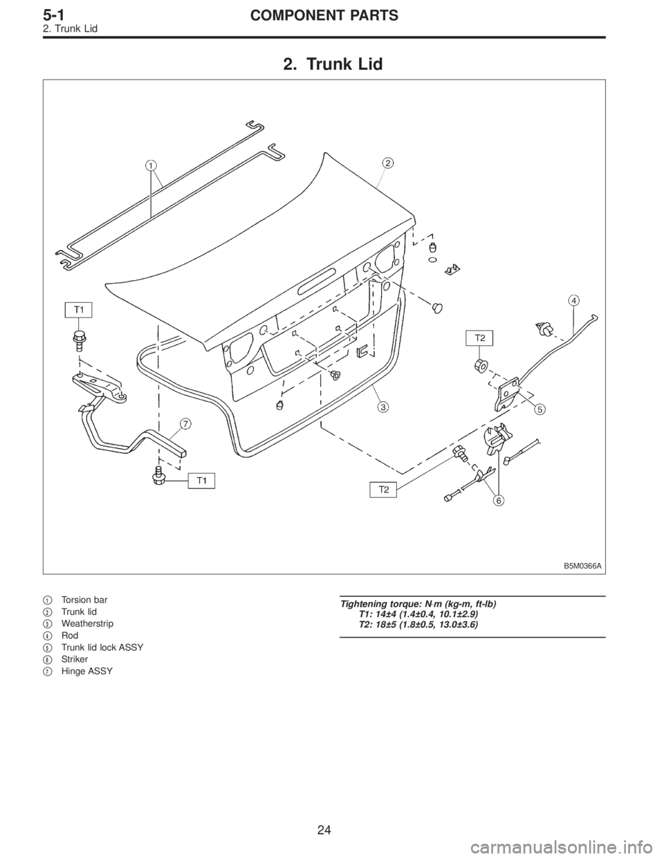
2. Trunk Lid
B5M0366A
�1Torsion bar
�
2Trunk lid
�
3Weatherstrip
�
4Rod
�
5Trunk lid lock ASSY
�
6Striker
�
7Hinge ASSY
Tightening torque: N⋅m (kg-m, ft-lb)
T1: 14±4 (1.4±0.4, 10.1±2.9)
T2: 18±5 (1.8±0.5, 13.0±3.6)
24
5-1COMPONENT PARTS
2. Trunk Lid
Page 1544 of 3342
G5M0144
2. Trunk Lid
A: REMOVAL
1. TRUNK LID
1) Open trunk lid.
2) Remove trunk lid mounting bolts and detach trunk lid
from hinges.
G5M0145
2. TORSION BAR
1) Open trunk lid. Remove torsion bars from hinge links
using ST.
ST 927780000 REMOVER
CAUTION:
Be careful because torsion bar quickly swings back
when released.
2) Remove the left and right torsion bars.
WARNING:
Be careful because trunk lid drops under its own
weight when torsion bars are removed.
G5M0146
3. TRUNK LID LOCK ASSEMBLY AND KEY
CYLINDER
1) Remove rod of lock assembly from rod holder of key
lock assembly.
2) Remove nuts which hold lock assembly and remove
lock assembly.
NOTE:
�Always remove rear skirt trim panel beforehand, if so
equipped.
�Be careful not to bend opener cable.
B5M0269A
3) Remove rod holder and detach key cylinder from trunk
lid.
35
5-1SERVICE PROCEDURE
2. Trunk Lid
Page 1545 of 3342
 Remove rear seats, center pillar lower cover, floor mat,
rear arch cover and side sill cover (on the driver’s side).
2) Remove all clips which hold cable.
3) Disconnec")
G5M0147
4. TRUNK LID OPENER
1) Remove rear seats, center pillar lower cover, floor mat,
rear arch cover and side sill cover (on the driver’s side).
2) Remove all clips which hold cable.
3) Disconnect cable from pull handle assembly.
4) Remove bolts and detach pull handle assembly.
5) Loosen bolts which hold lock assembly, and remove it.
6) Remove striker from trunk lid.
7) Disconnect cable from striker.
NOTE:
�Be careful not to bend or break cable.
�Basic model vehicles do not have trunk lid opener sys-
tem.
B5M0372A
B: INSTALLATION
Installation is in the reverse order of removal.
CAUTION:
�When installing cover to pull handle assembly,
observe the following:
�Be careful not to catch harness.
�Engage pull handle assembly pawls firmly.
�After installing opener cable, ensure it moves
smoothly.
�Apply a coat of grease to the rotary section of
hinges and contact surfaces of torsion bars.
�Apply grease to sliding surfaces of lock assembly
and striker.
B5M0270A
C: ADJUSTMENT
1. TRUNK LID
1) To adjust left-right lid positioning, loosen bolts which
hold trunk lid to hinges.
2) To adjust up-down lid alignment, place washer(s)
between trunk lid and hinges or move trunk lock assembly
up or down.
36
5-1SERVICE PROCEDURE
2. Trunk Lid
Page 1550 of 3342
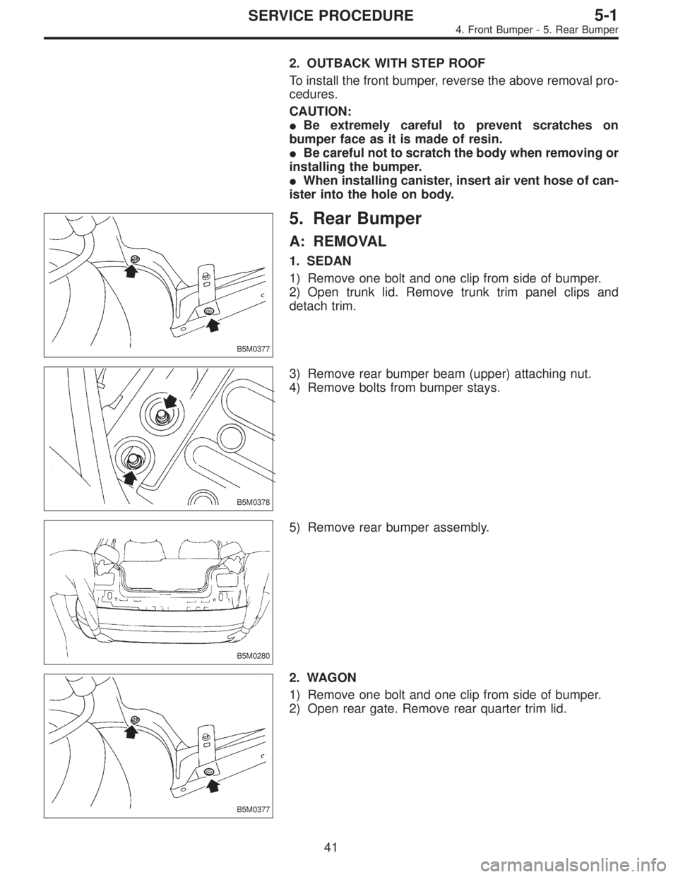
2. OUTBACK WITH STEP ROOF
To install the front bumper, reverse the above removal pro-
cedures.
CAUTION:
�Be extremely careful to prevent scratches on
bumper face as it is made of resin.
�Be careful not to scratch the body when removing or
installing the bumper.
�When installing canister, insert air vent hose of can-
ister into the hole on body.
B5M0377
5. Rear Bumper
A: REMOVAL
1. SEDAN
1) Remove one bolt and one clip from side of bumper.
2) Open trunk lid. Remove trunk trim panel clips and
detach trim.
B5M0378
3) Remove rear bumper beam (upper) attaching nut.
4) Remove bolts from bumper stays.
B5M0280
5) Remove rear bumper assembly.
B5M0377
2. WAGON
1) Remove one bolt and one clip from side of bumper.
2) Open rear gate. Remove rear quarter trim lid.
41
5-1SERVICE PROCEDURE
4. Front Bumper - 5. Rear Bumper

20
5-1SERVICE DATA
3. Datum Dimensions")
 Open trunk lid.
2) Remove trunk lid mounting bolts and detach trunk lid
from hinges.
G5M0145
2. TORSION BAR
1) Open trunk lid. Remove torsion bars from")