Page 3 of 3342
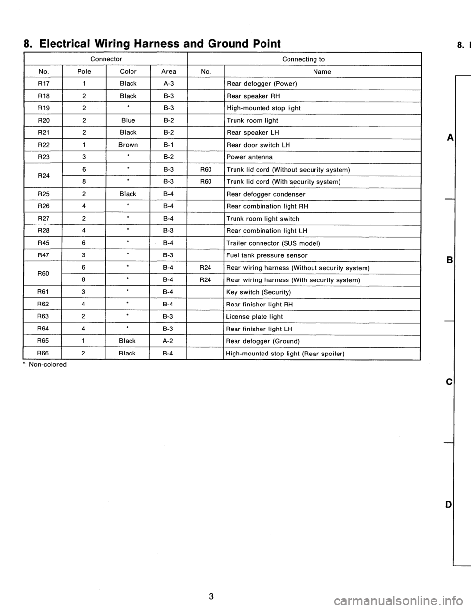
8
.
Electrical
Wiring
Harness
and
Ground
Point
Connector
Connecting
to
No
.
Pole
Color
Area
No
.
Name
R17
1
Black
A-3
Rear
defogger
(Power)
R18
2
Black
B-3
Rear
speaker
RH
R19
2B-3
High-mounted
stop
light
R20
2
Blue
B-2
Trunk
room
light
R21
2
Black
B-2
Rear
speaker
LH
R22
1
Brown
B-1
Rear
door
switch
LH
R23
3
B-2
Power
antenna
R24
6B-3
R60
Trunk
lid
cord(Without
security
system)
8
B-3
R60
Trunk
lid
cord
(With
security
system)
R25
2
Black
B-4
Rear
defogger
condenser
R26
4
B-4
Rear
combination
light
RH
R27
2
B-4
Trunk
room
light
switch
R28
4
B-3
Rear
combination
light
LH
R45
6
B-4
Trailer
connector
(SUS
model)
R47
3B-3Fueltank
pressure
sensor
R60
6B-4
R24
Rear
wiring
harness
(Without
security
system)
8B-4
R24
Rear
wiring
harness
(With
security
system)
R61
3B-4
Key
switch
(Security)
R62
4B-4
Rear
finisher
light
RH
R63
2B-3
License
plate
light
R64
4B-3
Rear
finisher
light
LH
R65
1
Black
A-2
Rear
defogger(Ground)
R66
2
Black
B-4
E
High-mounted
stop
light
(Rear
spoiler)
'
:
Non-colored
3
A
B
C
D
8
.
REAR
END
WIRING
HARNESS
AND
GROUND
POINT
OF
SEDAN
1
1
2
1
3
R65
1
R17
,
R19
4
\
R66
GD
A
~
~
R45
i
O
~~`
R18
''r
~
R25
R21
~
~O
\
R22
O
R20
R24
R47
~---
R23R2g
'
:
R60
R62
o
GB-9
0
~~,
.~I
~~I)~1
B6M0104B
2
R63R26
R64R27
R61~
~
GB-9
3
[D808]
B6M0823A
4
A
B
C
D
Page 220 of 3342
Connector
Connecting
to
No
.
Pole
Color
Area
No
.
Name
i1
22
Black
C-4
B36
i2
22
G4
B37
i3
22
Brown
C-4
B38
Bulkhead
wiring
harness
i4
20
Blue
C-4
B39
i5
15
Gray
C-4F!B
i6
10
C-4
Remote
control
rearview
mirror
switch
i10
16
Light
gray
B-3
i11
5
Light
blueB-3
Combination
meter
i12
16
Light
gray
B-3
Combination
meter
04
13
B-3
Combination
meter
05
6B-2
Fan
switch
07
16
Black
B-2
Mode
control
panel
08
6B-3
Rear
defogger
switch
09
6
Brown
B-3Cruise
control
main
switch
i20
4
Blue
B-2
B80
Bulkhead
wiring
harness
i22
10
B-2
Hazard
switch
i23
2
Brown
B-2
Glove
box
illumination
light
i24
1
G2
i25
3C-2Front
accessory
power
supply
i26
14
B-2
Radio
i27
2B-2
CD
player
illumination
light
i28
1
Black
C-2
Ground
i29
1
Black
C-2
Ground
(Radio)
i30
4B-2
Rear
window
defogger
timer
'
:
Non-colored
5
.
INSTRUMENT
PANEL
WIRING
HARNESS
AND
GROUND
POINT
9
RHD
model
1
23
AI
B
C
DI
1
2
3
5
Page 221 of 3342
Connector
Connecting
to
ole
Color
Area
No
.
Name
22
Black
C-4
B36
22
C-4
B37
lkh
ii
h
?2
Brown
C-4
B38
ead
w
r
ng
arness
Bu
20
Blue
C-4
B39
15
Gray
C-4
FIB
10
C-4
Remote
control
rearview
mirrorswitch
16
Light
gray
B-3
ii
5
Light
blue
B-3
Comb
nat
on
meter
16
Light
gray
B-3
Combination
meter
13
B-3
Combination
meter
6
B-2
Fan
switch
16
Black
B-2
Mode
control
panel
6
B-3
Rear
defogger
switch
6
Brown
B-3
Cruise
control
main
switch
4
Blue
B-2
B80
Bulkhead
wiring
harness
10
B-2
Hazard
switch
2
Brown
B-2
Glove
box
illumination
light
1
G2
F3
G2
ront
accessory
power
supply
14
8-2
Radio
2B-2
CD
player
illumination
light
1
Black
C-2
Ground
1
Black
G2
Ground
(Radio)
4
B-2
Rear
window
defogger
timer
5
.
INSTRUMENT
PANEL
WIRING
HARNESS
AND
GROUND
POINT
e
RHD
model
1
I
2
I
3
A
B
C
D
1
2
3
4
4
[D805]
B6M0849A
A
B
C
C
5
Page 222 of 3342
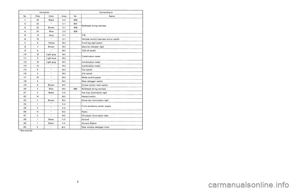
Connector
Connecting
to
No
.
Pole
Color
Area
No
.
Name
i1
22
Black
C-2
B36
i2
22C-1
B37
i3
22
Brown
C-1
B38
Bulkhead
wiring
harness
i4
20
Blue
C-2
B39
i5
15
Gray
C-1F1B
i6
10
C-1
Remote
control
rearview
mirrorswitch
i7
6
Yellow
B-2Front
fog
light
switch
i8
4
Brown
B-2Security
indicator
light
i9
6B-2
TCS
off
switch
i10
16
Light
gray
B-2
i11
5
Light
blueB-2
Combination
meter
i12
16
Light
gray
B-2
Combination
meter
i14
13
B-2
Combination
meter
05
6
B-3
Fan
switch
06
3
B-3
A/C
switch
07
16
B-3
Mode
control
panel
08
6B-3
Rear
defogger
switch
09
6
Brown
B-2
Cruise
control
main
switch
i20
4
Blue
B-3
B80
Bulkhead
wiring
harness
i212
Black
C-3
Ash
tray
illumination
light
i22
10
B-3
Hazard
switch
i23
2
Brown
B-4
Glove
box
illumination
light
i24
1
C-3
i25
3
C-3Front
accessory
power
supply
i26
14
B-3
Radio
i27
2B-3
CD
player
illumination
light
i28
1
Black
C-3
Ground
i29
1
Black
G3
Ground
(Radio)
i30
4
~
°
g-2
Rear
window
defogger
timer
'
:
Non-colored
8
.
Electrical
Wiring
Harness
and
Ground
Point
5
.
INSTRUMENT
PANEL
WIRING
HARNESS
AND
GROUND
POINT
9
LHD
model
1
23
A
B
CII
C
DI
3
1
23
Page 223 of 3342
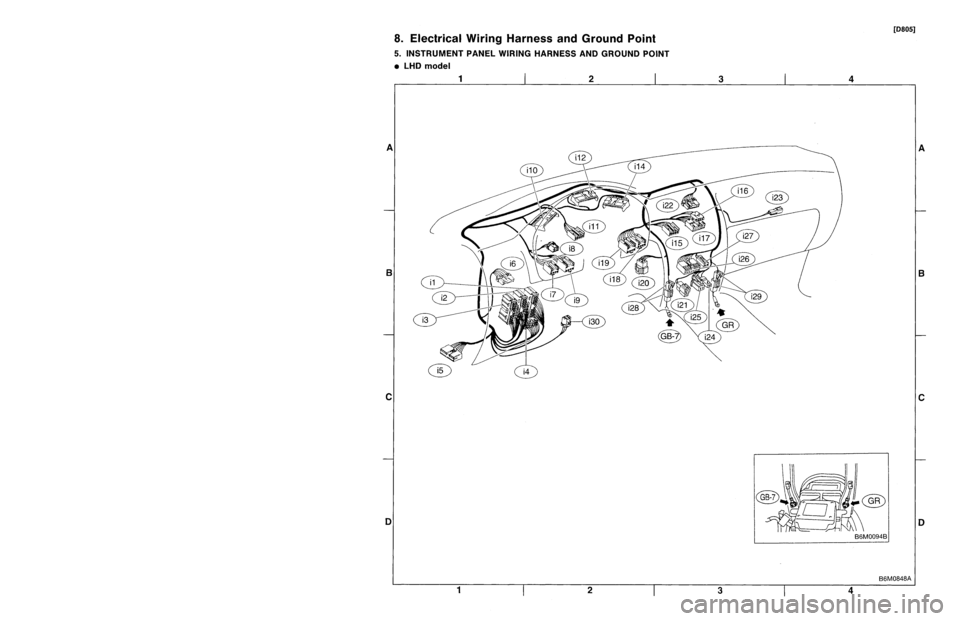
Connector
Connecting
to
ole
Color
Area
No
.
Name
?2
Black
G2
B36
?2
C-1
B37
lkh
ii
h
?2
Brown
C-1
B38ead
w
r
ng
arness
Bu
?0
Blue
G-2
B39
15
Gray
C-1FIB
10
C-1
Remote
control
rearview
mirrorswitch
6
Yellow
B-2
Front
fog
light
switch
4
Brown
B-2Security
indicator
light
6B-2
TCS
off
switch
16
Light
gray
B-2
ii
5
Light
blueB-2
Comb
nat
on
meter
16
Light
gray
B-2
Combination
meter
13
~
B-2
Combination
meter
6B-3
Fan
switch
3B-3
A/C
switch
16
B-3
Mode
control
panel
6
B-3
Rear
defogger
switch
6
Brown
8-2Cruise
control
main
switch
4
Blue
B-3B80
Bulkhead
wiring
harness
?
Black
C-3
Ash
trayillumination
light
0
B-3
Hazard
switch
?
Brown
B-4
Glove
box
illumination
light
1
C-3
3
C-3Front
accessory
power
supply
4B-3
Radio
2
B-3
CD
player
illumination
light
I
Black
C-3
Ground
I
Black
C-3
Ground
(Radio)
B-2
~
~
Rear
window
defogger
timer
3
8
.
Electrical
Wiring
Harness
andGround
Point
5
.
INSTRUMENT
PANEL
WIRING
HARNESS
AND
GROUND
POINT
e
LHD
model
[D805]
1
I
2
I
3
A
B
C
1
2
3
4
4
B6M0848A
A
B
C
Page 1549 of 3342
B5M0376
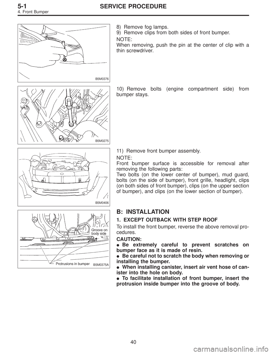
8) Remove fog lamps.
9) Remove clips from both sides of front bumper.
NOTE:
When removing, push the pin at the center of clip with a
thin screwdriver.
B5M0275
10) Remove bolts (engine compartment side) from
bumper stays.
B5M0406
11) Remove front bumper assembly.
NOTE:
Front bumper surface is accessible for removal after
removing the following parts:
Two bolts (on the lower center of bumper), mud guard,
bolts (on the side of bumper), front grille, headlight, clips
(on both sides of front bumper), clips (on the upper section
of bumper), and clips (on the lower section of bumper).
B5M0375A
B: INSTALLATION
1. EXCEPT OUTBACK WITH STEP ROOF
To install the front bumper, reverse the above removal pro-
cedures.
CAUTION:
�Be extremely careful to prevent scratches on
bumper face as it is made of resin.
�Be careful not to scratch the body when removing or
installing the bumper.
�When installing canister, insert air vent hose of can-
ister into the hole on body.
�To facilitate installation of front bumper, insert the
protrusion inside bumper into the groove of body.
40
5-1SERVICE PROCEDURE
4. Front Bumper
Page 1617 of 3342
G5M0409
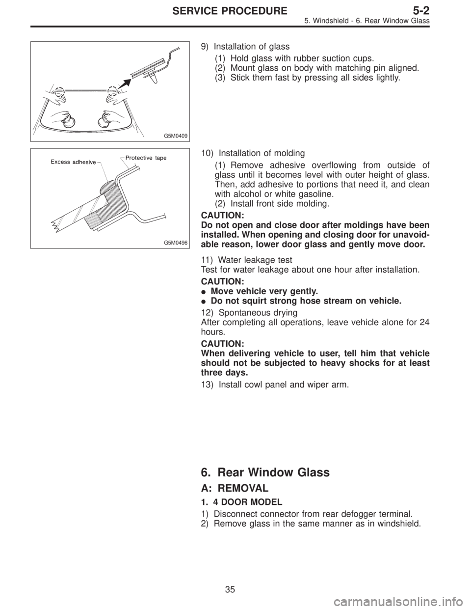
9) Installation of glass
(1) Hold glass with rubber suction cups.
(2) Mount glass on body with matching pin aligned.
(3) Stick them fast by pressing all sides lightly.
G5M0496
10) Installation of molding
(1) Remove adhesive overflowing from outside of
glass until it becomes level with outer height of glass.
Then, add adhesive to portions that need it, and clean
with alcohol or white gasoline.
(2) Install front side molding.
CAUTION:
Do not open and close door after moldings have been
installed. When opening and closing door for unavoid-
able reason, lower door glass and gently move door.
11) Water leakage test
Test for water leakage about one hour after installation.
CAUTION:
�Move vehicle very gently.
�Do not squirt strong hose stream on vehicle.
12) Spontaneous drying
After completing all operations, leave vehicle alone for 24
hours.
CAUTION:
When delivering vehicle to user, tell him that vehicle
should not be subjected to heavy shocks for at least
three days.
13) Install cowl panel and wiper arm.
6. Rear Window Glass
A: REMOVAL
1. 4 DOOR MODEL
1) Disconnect connector from rear defogger terminal.
2) Remove glass in the same manner as in windshield.
35
5-2SERVICE PROCEDURE
5. Windshield - 6. Rear Window Glass
Page 1618 of 3342
G5M0409
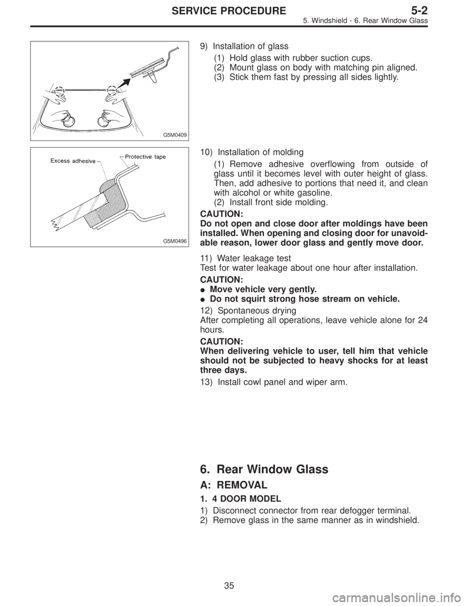
9) Installation of glass
(1) Hold glass with rubber suction cups.
(2) Mount glass on body with matching pin aligned.
(3) Stick them fast by pressing all sides lightly.
G5M0496
10) Installation of molding
(1) Remove adhesive overflowing from outside of
glass until it becomes level with outer height of glass.
Then, add adhesive to portions that need it, and clean
with alcohol or white gasoline.
(2) Install front side molding.
CAUTION:
Do not open and close door after moldings have been
installed. When opening and closing door for unavoid-
able reason, lower door glass and gently move door.
11) Water leakage test
Test for water leakage about one hour after installation.
CAUTION:
�Move vehicle very gently.
�Do not squirt strong hose stream on vehicle.
12) Spontaneous drying
After completing all operations, leave vehicle alone for 24
hours.
CAUTION:
When delivering vehicle to user, tell him that vehicle
should not be subjected to heavy shocks for at least
three days.
13) Install cowl panel and wiper arm.
6. Rear Window Glass
A: REMOVAL
1. 4 DOOR MODEL
1) Disconnect connector from rear defogger terminal.
2) Remove glass in the same manner as in windshield.
35
5-2SERVICE PROCEDURE
5. Windshield - 6. Rear Window Glass