Page 3 of 3342

R18
2
Black
B-3
Rear
speaker
RH
R19
2B-3
High-mounted
s")
8
.
Electrical
Wiring
Harness
and
Ground
Point
Connector
Connecting
to
No
.
Pole
Color
Area
No
.
Name
R17
1
Black
A-3
Rear
defogger
(Power)
R18
2
Black
B-3
Rear
speaker
RH
R19
2B-3
High-mounted
stop
light
R20
2
Blue
B-2
Trunk
room
light
R21
2
Black
B-2
Rear
speaker
LH
R22
1
Brown
B-1
Rear
door
switch
LH
R23
3
B-2
Power
antenna
R24
6B-3
R60
Trunk
lid
cord(Without
security
system)
8
B-3
R60
Trunk
lid
cord
(With
security
system)
R25
2
Black
B-4
Rear
defogger
condenser
R26
4
B-4
Rear
combination
light
RH
R27
2
B-4
Trunk
room
light
switch
R28
4
B-3
Rear
combination
light
LH
R45
6
B-4
Trailer
connector
(SUS
model)
R47
3B-3Fueltank
pressure
sensor
R60
6B-4
R24
Rear
wiring
harness
(Without
security
system)
8B-4
R24
Rear
wiring
harness
(With
security
system)
R61
3B-4
Key
switch
(Security)
R62
4B-4
Rear
finisher
light
RH
R63
2B-3
License
plate
light
R64
4B-3
Rear
finisher
light
LH
R65
1
Black
A-2
Rear
defogger(Ground)
R66
2
Black
B-4
E
High-mounted
stop
light
(Rear
spoiler)
'
:
Non-colored
3
A
B
C
D
8
.
REAR
END
WIRING
HARNESS
AND
GROUND
POINT
OF
SEDAN
1
1
2
1
3
R65
1
R17
,
R19
4
\
R66
GD
A
~
~
R45
i
O
~~`
R18
''r
~
R25
R21
~
~O
\
R22
O
R20
R24
R47
~---
R23R2g
'
:
R60
R62
o
GB-9
0
~~,
.~I
~~I)~1
B6M0104B
2
R63R26
R64R27
R61~
~
GB-9
3
[D808]
B6M0823A
4
A
B
C
D
Page 217 of 3342
WIRING
DIAGRAM
[osoa1
6-3
6
.
Wiring
Diagram
F2
100
Twisted
wire
LL
7
-
---
-
---------
-
FtP1
Transmission
control
module
Check
Data
link
connectorconnector
879
EEE
878
a
B56
:c
Ref
.
to
Engine
electrical
system
.
881
Diagnosis
PEterminal
B82
Q1
-
Diagnosis
connector
Front
~--~~
ABS
sensorLH
II
---------------
------_-----_--_----_J
Twisted
wire
ABS
G
sensor
86
B15
P8
(Outback
model
:
Brown)
O
(Other
models
:
Gray)
(Other
models)
(Outback
model)
(Gray)
86
Front
m--F-I
ABS
sensor
RH
n
(Outback
(Other
(Outback
(Other
model)
models)
model)
models)
RearABS
Rear
ABS
sensor
RH
sensor
LH
------------------
P11
1
01
P-am
B78
(Yellow)
879
(Gray)
F1
856
(Black)
1
4
1
4
56
10131
1
1
12131
45
6
8
10
56
88
99
10
111
1314
45678
1
11
1
12
1
13
1
14
1
15
1
16
11
/1
16
1
19
12U]
B82
(Black)
1
456
8100
(Blue)
4
6
171619
111
1
1415161
18192010BU82-04B
3
Page 219 of 3342
6-3
toso2a1
WIRING
DIAGRAM
6
.
Wiring
Diagram
6
.
Wiring
Diagram
24
.
REAR
WINDOW
DEFOGGER
SYSTEM
Reardefogger
switch
Rear
defogger
R25
condenser
0
L
L
F
B97
R1
(Sedan)
R17
Rear
defogger
(Sedan)
R31
D33D40
(Wagon)
RL
R
RL
E
D48
=
B
D33
R25
(Black)
i18
i30
1414
1
4
i4
(Blue)
1
M10
BU52-02
2
GD
Rear
Page 220 of 3342
Connector
Connecting
to
No
.
Pole
Color
Area
No
.
Name
i1
22
Black
C-4
B36
i2
22
G4
B37
i3
22
Brown
C-4
B38
Bulkhead
wiring
harness
i4
20
Blue
C-4
B39
i5
15
Gray
C-4F!B
i6
10
C-4
Remote
control
rearview
mirror
switch
i10
16
Light
gray
B-3
i11
5
Light
blueB-3
Combination
meter
i12
16
Light
gray
B-3
Combination
meter
04
13
B-3
Combination
meter
05
6B-2
Fan
switch
07
16
Black
B-2
Mode
control
panel
08
6B-3
Rear
defogger
switch
09
6
Brown
B-3Cruise
control
main
switch
i20
4
Blue
B-2
B80
Bulkhead
wiring
harness
i22
10
B-2
Hazard
switch
i23
2
Brown
B-2
Glove
box
illumination
light
i24
1
G2
i25
3C-2Front
accessory
power
supply
i26
14
B-2
Radio
i27
2B-2
CD
player
illumination
light
i28
1
Black
C-2
Ground
i29
1
Black
C-2
Ground
(Radio)
i30
4B-2
Rear
window
defogger
timer
'
:
Non-colored
5
.
INSTRUMENT
PANEL
WIRING
HARNESS
AND
GROUND
POINT
9
RHD
model
1
23
AI
B
C
DI
1
2
3
5
Page 221 of 3342
Connector
Connecting
to
ole
Color
Area
No
.
Name
22
Black
C-4
B36
22
C-4
B37
lkh
ii
h
?2
Brown
C-4
B38
ead
w
r
ng
arness
Bu
20
Blue
C-4
B39
15
Gray
C-4
FIB
10
C-4
Remote
control
rearview
mirrorswitch
16
Light
gray
B-3
ii
5
Light
blue
B-3
Comb
nat
on
meter
16
Light
gray
B-3
Combination
meter
13
B-3
Combination
meter
6
B-2
Fan
switch
16
Black
B-2
Mode
control
panel
6
B-3
Rear
defogger
switch
6
Brown
B-3
Cruise
control
main
switch
4
Blue
B-2
B80
Bulkhead
wiring
harness
10
B-2
Hazard
switch
2
Brown
B-2
Glove
box
illumination
light
1
G2
F3
G2
ront
accessory
power
supply
14
8-2
Radio
2B-2
CD
player
illumination
light
1
Black
C-2
Ground
1
Black
G2
Ground
(Radio)
4
B-2
Rear
window
defogger
timer
5
.
INSTRUMENT
PANEL
WIRING
HARNESS
AND
GROUND
POINT
e
RHD
model
1
I
2
I
3
A
B
C
D
1
2
3
4
4
[D805]
B6M0849A
A
B
C
C
5
Page 222 of 3342

Connector
Connecting
to
No
.
Pole
Color
Area
No
.
Name
i1
22
Black
C-2
B36
i2
22C-1
B37
i3
22
Brown
C-1
B38
Bulkhead
wiring
harness
i4
20
Blue
C-2
B39
i5
15
Gray
C-1F1B
i6
10
C-1
Remote
control
rearview
mirrorswitch
i7
6
Yellow
B-2Front
fog
light
switch
i8
4
Brown
B-2Security
indicator
light
i9
6B-2
TCS
off
switch
i10
16
Light
gray
B-2
i11
5
Light
blueB-2
Combination
meter
i12
16
Light
gray
B-2
Combination
meter
i14
13
B-2
Combination
meter
05
6
B-3
Fan
switch
06
3
B-3
A/C
switch
07
16
B-3
Mode
control
panel
08
6B-3
Rear
defogger
switch
09
6
Brown
B-2
Cruise
control
main
switch
i20
4
Blue
B-3
B80
Bulkhead
wiring
harness
i212
Black
C-3
Ash
tray
illumination
light
i22
10
B-3
Hazard
switch
i23
2
Brown
B-4
Glove
box
illumination
light
i24
1
C-3
i25
3
C-3Front
accessory
power
supply
i26
14
B-3
Radio
i27
2B-3
CD
player
illumination
light
i28
1
Black
C-3
Ground
i29
1
Black
G3
Ground
(Radio)
i30
4
~
°
g-2
Rear
window
defogger
timer
'
:
Non-colored
8
.
Electrical
Wiring
Harness
and
Ground
Point
5
.
INSTRUMENT
PANEL
WIRING
HARNESS
AND
GROUND
POINT
9
LHD
model
1
23
A
B
CII
C
DI
3
1
23
Page 223 of 3342

Connector
Connecting
to
ole
Color
Area
No
.
Name
?2
Black
G2
B36
?2
C-1
B37
lkh
ii
h
?2
Brown
C-1
B38ead
w
r
ng
arness
Bu
?0
Blue
G-2
B39
15
Gray
C-1FIB
10
C-1
Remote
control
rearview
mirrorswitch
6
Yellow
B-2
Front
fog
light
switch
4
Brown
B-2Security
indicator
light
6B-2
TCS
off
switch
16
Light
gray
B-2
ii
5
Light
blueB-2
Comb
nat
on
meter
16
Light
gray
B-2
Combination
meter
13
~
B-2
Combination
meter
6B-3
Fan
switch
3B-3
A/C
switch
16
B-3
Mode
control
panel
6
B-3
Rear
defogger
switch
6
Brown
8-2Cruise
control
main
switch
4
Blue
B-3B80
Bulkhead
wiring
harness
?
Black
C-3
Ash
trayillumination
light
0
B-3
Hazard
switch
?
Brown
B-4
Glove
box
illumination
light
1
C-3
3
C-3Front
accessory
power
supply
4B-3
Radio
2
B-3
CD
player
illumination
light
I
Black
C-3
Ground
I
Black
C-3
Ground
(Radio)
B-2
~
~
Rear
window
defogger
timer
3
8
.
Electrical
Wiring
Harness
andGround
Point
5
.
INSTRUMENT
PANEL
WIRING
HARNESS
AND
GROUND
POINT
e
LHD
model
[D805]
1
I
2
I
3
A
B
C
1
2
3
4
4
B6M0848A
A
B
C
Page 1650 of 3342
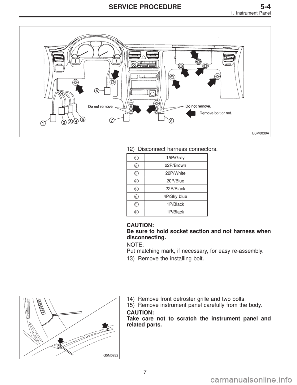
B5M0030A
12) Disconnect harness connectors.
�115P/Gray
�
222P/Brown
�
322P/White
�
420P/Blue
�
522P/Black
�
64P/Sky blue
�
71P/Black
�
81P/Black
CAUTION:
Be sure to hold socket section and not harness when
disconnecting.
NOTE:
Put matching mark, if necessary, for easy re-assembly.
13) Remove the installing bolt.
G5M0282
14) Remove front defroster grille and two bolts.
15) Remove instrument panel carefully from the body.
CAUTION:
Take care not to scratch the instrument panel and
related parts.
7
5-4SERVICE PROCEDURE
1. Instrument Panel


R17
Rear
defogger
(Sed")