Page 4 of 3342
![SUBARU LEGACY 1997 Service Repair Manual 4-4
LM13-1]
BRAKES
13
.
Anti-lock
Brake
System
(ABS)
[5
.3i
Type]
13
.
Anti-lock
Brake
System
(ABS)
[5
.3i
Type]
1
.
FEATURE
*
This
ABS
5
.3i
type
incorporates
the
hydraulic
control
unit,
ABS
contr](/manual-img/17/57434/w960_57434-3.png "SUBARU LEGACY 1997 Service Repair Manual 4-4
LM13-1]
BRAKES
13
.
Anti-lock
Brake
System
(ABS)
[5
.3i
Type]
13
.
Anti-lock
Brake
System
(ABS)
[5
.3i
Type]
1
.
FEATURE
*
This
ABS
5
.3i
type
incorporates
the
hydraulic
control
unit,
ABS
contr")
4-4
LM13-1]
BRAKES
13
.
Anti-lock
Brake
System
(ABS)
[5
.3i
Type]
13
.
Anti-lock
Brake
System
(ABS)
[5
.3i
Type]
1
.
FEATURE
*
This
ABS
5
.3i
type
incorporates
the
hydraulic
control
unit,
ABS
control
module,
valve
relay
and
motor
relay
in
one
unit
for
betterproductivity
and
lightweight
.
*
The
ABS
(Anti-lock
brake
system)
electrically
controls
brake
fluid
pressure
to
prevent
wheel
"lock"
during
braking
on
slippery
road
surfaces,
thereby
improving
directional/steering
stability
as
well
as
shortening
the
braking
distance
.
*
If
the
ABS
becomes
inoperative,
the
fail-safe
system
activates
to
ensure
it
acts
asa
conventional
brake
system
.
The
warning
light
also
comes
on
to
indicate
that
the
ABS
is
malfunctioning
.
"
The
front-and-rear
wheels
utilize
a
4-sensor,
4-channel
control
design
:
the
front
wheels
havean
independent
control
design*1
and
the
rear
wheels
have
a
select
low
control
design*2
.
*1
:
A
system
which
independently
controls
fluid
pressure
to
left
and
right
front
wheels
.
*2
:
A
system
which
provides
the
same
fluid
pressure
control
for
the
two
rear
wheels
if
either
wheel
starts
to"lock
."
10
ABS
control
moduleand
hydraulic
control
unit
(ABSCM&H/U)
Proportioning
valve
OO
Diagnosisconnector
OO
ABS
warning
light
OO
Data
link
connector
(for
SUBARU
select
monitor)
OO
Transmission
control
module
(only
AT
vehicle)
Tone
wheel
OO
ABS
sensor
09
Wheel
cylinder
O
G
sensor
(only
AWD
vehicle)
>>
Brake
switch
D
Master
cylinder
?15A
2
Page 26 of 3342
![SUBARU LEGACY 1997 Service Repair Manual
SERVICE
PROCEDURE
[W25D21
4-4
25
.
ABS
Control
Module
and
Hydraulic
Control
Unit
(ABSCM&H/U)
[ABS
5
.3i
Type]
Diagnosis
connector
--J
1
I`
--~
~
-
Diagnosis
terminals
3
terminal
6
terminal
-](/manual-img/17/57434/w960_57434-25.png "SUBARU LEGACY 1997 Service Repair Manual
SERVICE
PROCEDURE
[W25D21
4-4
25
.
ABS
Control
Module
and
Hydraulic
Control
Unit
(ABSCM&H/U)
[ABS
5
.3i
Type]
Diagnosis
connector
--J
1
I`
--~
~
-
Diagnosis
terminals
3
terminal
6
terminal
-")
SERVICE
PROCEDURE
[W25D21
4-4
25
.
ABS
Control
Module
and
Hydraulic
Control
Unit
(ABSCM&H/U)
[ABS
5
.3i
Type]
Diagnosis
connector
--J
1
I`
--~
~
''-
Diagnosis
terminals
3
terminal
6
terminal
-
/
B4M0082D
D
:
ABS
SEQUENCE
CONTROL
1)
Under
the
ABS
sequence
control,
after
thehydraulic
unit
solenoid
valve
is
driven,
theoperation
of
thehydrau-
lic
unit
can
be
checked
by
means
of
the
brake
tester
or
pressure
gauge
.
2)
ABS
sequence
control
can
be
started
by
diagnosis
connector
or
select
monitor
.
1
.
OPERATIONAL
GUIDELINES
OF
THE
ABS
SEQUENCE
CONTROL
WITH
DIAGNOSIS
CONNECTOR
1)
Connect
diagnosis
terminals
to
terminals
No
.
3
andNo
.
6
of
the
diagnosis
connector
beside
driver's
seat
heater
unit
.
2)
Setthe
speed
of
all
wheels
at
4
km/h
(2
MPH)
or
less
.
3)
Turn
ignition
switch
OFF
.
4)
Within
0
.5
seconds
after
the
ABS
warning
light
goes
out,
depress
the
brake
pedal
and
hold
it
immediately
after
ignition
switch
is
turned
to
ON
.
CAUTION
:
Do
not
depress
the
clutch
pedal
.
NOTE
:
*
When
the
ignition
switch
is
setto
on,the
brake
pedal
must
not
be
depressed
.
Engine
must
not
operate
.
5)
After
completion
of
ABS
sequence
control,
turn
ignition
switch
OFF
.
2
.
OPERATIONAL
GUIDELINES
OF
THE
ABS
SEQUENCE
CONTROL
WITH
SELECT
MONITOR
NOTE
:
In
the
event
of
any
trouble,
the
sequence
control
may
not
be
operative
.
In
such
a
case,
activate
the
sequence
control,
referring
to
"OPERATIONAL
GUIDELINES
OF
THE
ABS
SEQUENCE
CONTROL
WITHDIAGNOSIS
CONNEC-
TOR
"
.
<
Ref
.
to
4-4
[W25D1],*10>
1)
Connect
select
monitor
to
data
link
connector
beside
driver's
seat
heater
unit
.
2)
Turn
ignition
switch
ON
.
3)
Put
select
monitor
to
ABS
mode
.
11
Page 27 of 3342
4-4
[W25D2]
SERVICE
PROCEDURE
25
.
ABS
Control
Module
and
Hydraulic
Control
Unit
(ABSCM&H/U)
[ABS
5
.3i
Type]
[F-101
O
ENT
B4M0635
ABS
FUNCTION
CHECK
MODE
B4M0997
I
BRAKE
ON
KEEP100-150
B4M0998
I
MODE
START
PRESS
ENT
KEY
B4M0999
FUNCTION
START
UNABLE
SWIM
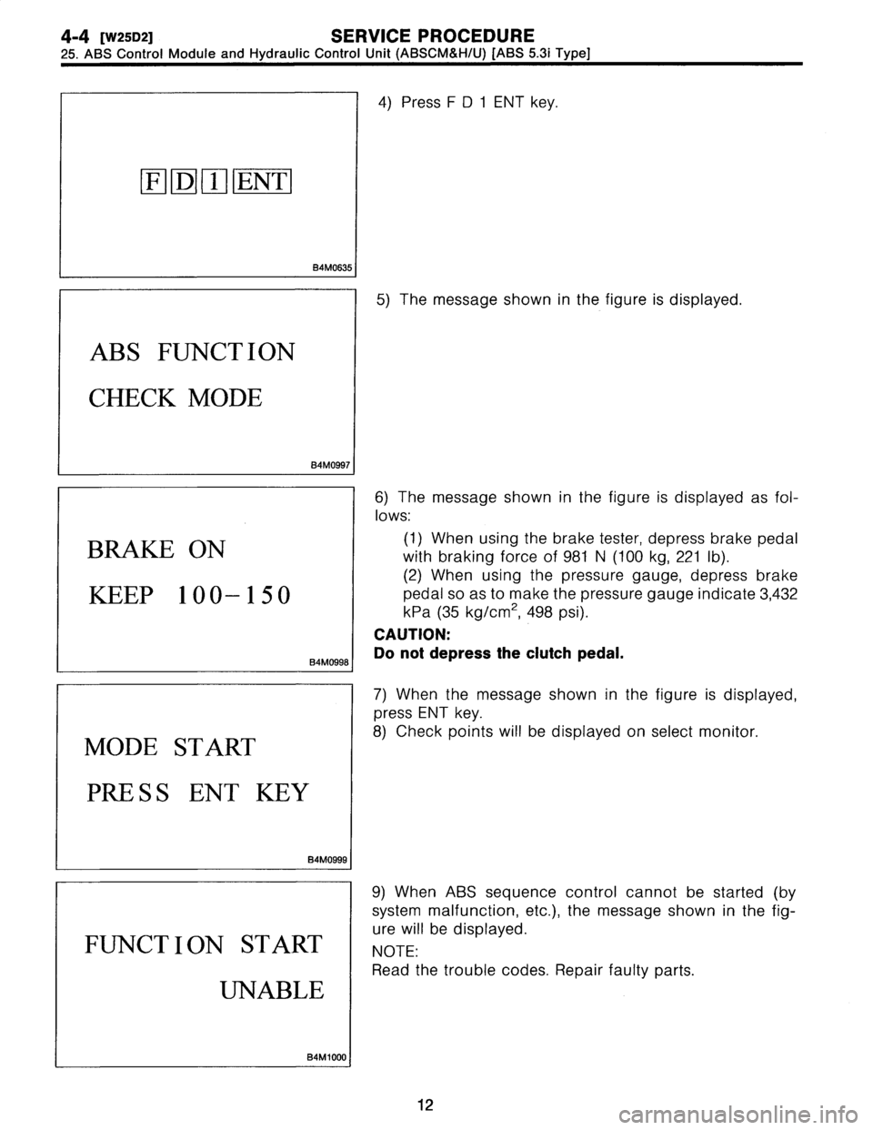
4)
Press
FD
1
ENT
key
.
5)
The
message
shown
in
the
figure
is
displayed
.
6)
The
message
shown
in
the
figure
is
displayed
as
fol-
lows
:
(1)
When
using
the
brake
tester,
depress
brake
pedal
with
braking
force
of
981
N
(100
kg,
221
Ib)
.
(2)
When
using
the
pressure
gauge,
depress
brake
pedalsoas
to
make
the
pressure
gauge
indicate
3,432
kPa
(35
kg/cm2,
498
psi)
.
CAUTION
:
Do
not
depress
the
clutch
pedal
.
7)
When
the
message
shown
in
the
figure
is
displayed,
press
ENT
key
.
8)
Check
points
will
be
displayed
on
select
monitor
.
9)
WhenABS
sequence
control
cannot
be
started
(by
system
malfunction,
etc
.),
the
message
shown
in
the
fig-
ure
will
be
displayed
.
NOTE
:
Read
the
trouble
codes
.
Repair
faulty
parts
.
12
Page 28 of 3342
![SUBARU LEGACY 1997 Service Repair Manual
SERVICE
PROCEDURE
[w2sDa1
4-4
25
.
AgS
Control
Module
and
Hydraulic
Control
Unit
(ABSCM&H/U)
[ABS
5
.3i
Type]
AB
S
FUNCTION
CHECK
END
B4M1030
MODE
RESTART?
0
:
YE
S
1
:
NO
H4M
1144
10)
After](/manual-img/17/57434/w960_57434-27.png "SUBARU LEGACY 1997 Service Repair Manual
SERVICE
PROCEDURE
[w2sDa1
4-4
25
.
AgS
Control
Module
and
Hydraulic
Control
Unit
(ABSCM&H/U)
[ABS
5
.3i
Type]
AB
S
FUNCTION
CHECK
END
B4M1030
MODE
RESTART?
0
:
YE
S
1
:
NO
H4M
1144
10)
After")
SERVICE
PROCEDURE
[w2sDa1
4-4
25
.
AgS
Control
Module
and
Hydraulic
Control
Unit
(ABSCM&H/U)
[ABS
5
.3i
Type]
AB
S
FUNCTION
CHECK
END
B4M1030
MODE
RESTART?
0
:
YE
S
1
:
NO
H4M
1144
10)
After
completion
of
ABS
sequence
control
.
11)
Press0key
tostart
ABS
sequence
control
again
and
press
1
key
to
end
.
3
.
CONDITIONS
FOR
COMPLETIONOF
ABS
SEQUENCE
CONTROL
When
the
following
conditions
develop,
the
ABS
sequence
control
stops
and
ABS
operation
is
returned
to
the
normal
control
mode
.
1)
When
the
speed
ofat
least
one
wheel
reaches
10
km/h
(6
MPH)
.
2)
When
terminal
No
.
3
or
No
.
6
are
separated
from
diag-
nosis
terminals
.
(When
select
monitor
is
not
used
.)
3)
When
the
brakepedal
is
released
during
sequence
control
and
the
braking
lamp
switch
is
set
to
off
.
4)
When
brake
pedal
is
depressed
afterignition
key
is
turned
to
ON,
and
before
ABS
warning
light
goes
out
.
(When
select
monitor
is
not
used
.)
5)
When
brakepedal
is
not
depressed
after
ignition
key
is
turned
to
ON,
acrd
within
0
.5
seconds
after
ABS
warn-
ing
light
goes
out
.
(When
select
monitor
is
not
used
.)
6)
After
completion
of
the
sequence
control
.
7)
When
malfunction
is
detected
.
(When
select
monitor
is
used
.)
13
Page 29 of 3342

4-4
[W25D4]
SERVICE
PROCEDURE
25
.
ABS
Control
Module
and
Hydraulic
Control
Unit
(ABSCM&H/U)
[ABS
5
.3i
Type)
4
.
CONDITIONS
FORABS
SEQUENCE
CONTROL
4
km/h
Speed
of
all
wheels
HIGF
Terminal
No
.3
and
No
.6
LOV1
Operational
guide
lineofIgnition
key
switch
O
sequence
OFF
control
O
ABS
warning
light
OFF
HIGF
Stop
light
switch
LO"
HIGF
AT
ABS
signal
LOW
Valve
relay
ON
OFF
FL
outlet
valve
ON
OFF
FL
inlet
valve
O
NOFF
Operational
FR
outlet
valve
ON
OFF
pattern
of
ON
sequence
FR
inlet
valve
OFF
control
RR
outlet
valve
OFF
RR
inlet
valve
ON
OAF
RL
outlet
valve
OFF
RL
inlet
valve
ONOFF
Pump
motor
OFF
Operational
Pressure
of
master
cylinder
pressure
of
Pressure
of
FLwheel
cylinder
Pressure
of
FR
wheel
cylinder
sequence
Pressure
of
RR
wheel
cylinder
control
Pressure
of
RL
wheel
cylinder
Unit
:
second
B4M1001A
I
NOTE
:
*
When
select
monitor
is
used,
control
operation
starts
at
point
A
.
The
patterns
from
IGN
key
ON
to
the
point
A
show
that
operation
is
started
by
diagnosis
connector
.
HIGH
means
high
voltage
.
LOW
means
low
voltage
.
14
Page 33 of 3342
BRAKES
[ABS
5
.3i
TYPE]
[TZBi]
4-4d
2
.
Pre-inspection
B
:
ELECTRICAL
INSPECTION
1
.
WARNING
LIGHT
ILLUMINATION
PATTERN
START
ON
r~
ON
OFF
Ignition
key
switch
Illuminates
.
Goes
out
.
Goes
out
.
ABS
warning
light1.5s
4
111
B4M0781A
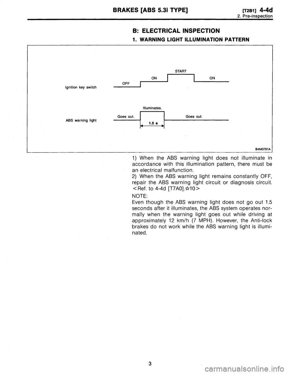
1)
When
the
ABS
warning
light
does
not
illuminate
in
accordance
with
this
illumination
pattern,
there
must
be
an
electrical
malfunction
.
2)
When
the
ABS
warning
light
remains
constantly
OFF,
repair
the
ABS
warning
light
circuit
or
diagnosis
circuit
.
.
to
4-4d
[T7A0]
.*10>
NOTE
:
Even
though
the
ABS
warning
light
does
not
go
out
1
.5
seconds
after
it
illuminates,
the
ABS
system
operates
nor-
mally
when
the
warning
light
goes
out
while
driving
at
approximately
12
km/h
(7
MPH)
.
However,
the
Anti-lock
brakes
do
not
work
while
the
ABS
warning
light
is
illumi-
nated
.
3
Page 40 of 3342
BRAKES
[ABS
5
.31
TYPE]
[rsao]
4-4d
6
.
Diagnostics
Chart
for
On-board
Diagnosis
System
I
TROUBLE
OCCURS
.I
Is
Select
Monitor
available?
I
Yes
1
10
.
Diagnostic
Chart
with
Select
1
Monitor
.
Ask
the
customer
when
and
how
the
trouble
occurred
using
interview
check
list
.
6
.
Diagnostics
Chart
for
On-board
Diagnosis
System
A
:
BASIC
DIAGNOSTICS
PROCEDURE
I
PRE-INSPECTION
I
I
CALLING
UPA
TROUBLE
CODE
.
I
No
trouble
code
is
readable
.
Inspection
using
Diagnostic
Chart
for
Warning
Light
Failure
.
Record
all
trouble
codes
.
Only
the
start
code
is
issued
.
Trouble
codes
are
issued
.
Perform
diagnostics
in
accordance
with
trouble
code
.
Trouble
code
I
Repair
.
designated
.
Clear
memory
.
I
INSPECTION
MODE
I
I
CALLING
UPA
TROUBLE
CODE
.
Only
the
star
t
code
is
issued
.
CONFIRMATION
TEST
END
Inspection
using
General
Diagnostics
chart
.
B4M
1051
A
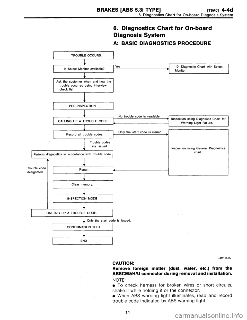
CAUTION
:
Remove
foreign
matter
(dust,
water,
etc
.)
from
the
ABSCM&H/U
connector
during
removal
and
installation
.
NOTE
:
e
To
check
harness
for
broken
wires
or
short
circuits,
shake
it
while
holding
it
or
the
connector
.
*
When
ABS
warning
light
illuminates,
read
and
record
trouble
code
indicated
by
ABS
warning
light
.
11
Page 41 of 3342

4-4d
[TSBO]
BRAKES
[ABS
5
.31
TYPE]
6
.
Diagnostics
Chart
for
On-board
Diagnosis
System
B
:
CHECK
LIST
FOR
INTERVIEW
Check
the
following
items
about
the
vehicle's
state
.
1
.
THE
STATE
OF
THE
ABS
WARNING
LIGHT
ABS
warning
light
O
Always
comes
on
.
D
Sometimes
O
Onlyonce
O
Does
not
come
on
o
When
/how
long
does
it
come
on?
:
Ignition
key
position
O
LOCK
D
ACC
OON
(before
starting
engine)
D
START
O
On
afterstarting
(Engine
is
running)
O
On
after
starting
(Engine
is
stop)
Timing
O
Immediately
afterignition
is
ON
.
O
Immediately
after
ignition
starts
.
O
When
advancing
km/h
to
km/h
MPH
to
MPH
D
While
traveling
at
a
constant
speed
km/h
MPH
D
When
decelerating
km/h
to
km/h
MPH
to
MPH
OWhen
turning
to
right
Steering
angle
:
deg
Steering
time
:
sec
D
When
turning
to
left
Steering
angle
:
deg
Steering
time
:
sec
D
When
moving
other
electrical
parts
Parts
name
Operating
condition
2
.
SYMPTOMS
ABS
operating
D
Performsno
work
.
condition
D
Operates
only
when
abruptly
applying
brakes
.
Vehicle
speed
:
km/h
MPH
~
How
to
step
on
brake
pedal
a)
Operating
time
:
sec
b)
Operating
noise
:
O
Produce
/
D
Does
not
produce
oWhat
kind
of
noise?
O
Knock
O
Gong
gong
D
Bong
a
Buzz
D
Gong
gong
buzz
O
Others
c)
Reaction
force
of
brake
pedal
O
Stick
O
Press
down
once
with
a
clunk
O
Press
and
released
D
Others
12