Page 1096 of 3342
G4M0492
3) Remove nut (do not remove bolt.) securing transverse
link to crossmember.
4) Remove two bolts securing bushing bracket of trans-
verse link to vehicle body at rear bushing location.
G4M0493
5) Extract ball joint from housing.
6) Remove bolt securing transverse link to crossmember
and extract transverse link from crossmember.
G4M0494
B: DISASSEMBLY
1. FRONT BUSHING
Using ST, press front bushing out of place.
ST 927680000 INSTALLER & REMOVER SET
G4M0495
2. REAR BUSHING
1) Scribe an aligning mark on transverse link and rear
bushing.
2) Loosen nut and remove rear bushing.
C: INSPECTION
1) Check transverse link for wear, damage and cracks,
and correct or replace if defective.
2) Check bushings for cracks, wear,damage and creeping.
3) Check rear bushing for oil leaks.
4) If defective, replace with new one.
17
4-1SERVICE PROCEDURE
2. Front Transverse Link
Page 1097 of 3342
 Install rear bushing to")
G4M0496
D: ASSEMBLY
1. FRONT BUSHING
To reassemble, reverse disassembly procedures.
CAUTION:
Install front bushing in correct direction, as shown in
figure.
2. REAR BUSHING
1) Install rear bushing to transverse link and align aligning
marks scribed on the two.
2) Tighten self-locking nut.
CAUTION:
�Discard loosened self-locking nut and replace with a
new one.
�While holding rear bushing so as not to change
position of aligning marks, tighten self-locking nut.
Tightening torque:
186±10 N⋅m (19.0±1.0 kg-m, 137±7 ft-lb)
E: INSTALLATION
1) Temporarily tighten the two bolts used to secure rear
bushing of the transverse link to body.
NOTE:
These bolts should be tightened to such an extent that they
can still move back and forth in the oblong shaped hole in
the bracket (which holds the bushing).
2) Install bolts used to connect transverse link to cross-
member and temporarily tighten with nut.
CAUTION:
Discard loosened self-locking nut and replace with a
new one.
3) Insert ball joint into housing.
18
4-1SERVICE PROCEDURE
2. Front Transverse Link
Page 1109 of 3342
G4M0524
B: DISASSEMBLY
1. FRONT BUSHING
Using ST, press front bushing out of place.
ST 927720000 INSTALLER & REMOVER SET
G4M0525
2. REAR BUSHING
1) Remove housing. Refer to“4-2 WHEELS AND AXLES”
for removal procedures.
2) Using ST, press rear bushing out of place.
ST 927730000 INSTALLER & REMOVER SET
C: INSPECTION
Check trailing links for bends, corrosion or damage.
30
4-1SERVICE PROCEDURE
7. Rear Trailing Link
Page 1110 of 3342
D: ASSEMBLY
To assemble, reverse above disassembly procedures.
B4M0226A
1. FRONT BUSHING
Using ST, press bushing into trailing link.
ST 927720000 INSTALLER & REMOVER SET
CAUTION:
When installing bushing, turn ST plunger upside down
and press it until plunger end surface contacts trailing
link end surface.
G4M0924
CAUTION:
Install front bushing in the proper direction, as shown
in figure.
31
4-1SERVICE PROCEDURE
7. Rear Trailing Link
Page 1115 of 3342
G4M0531
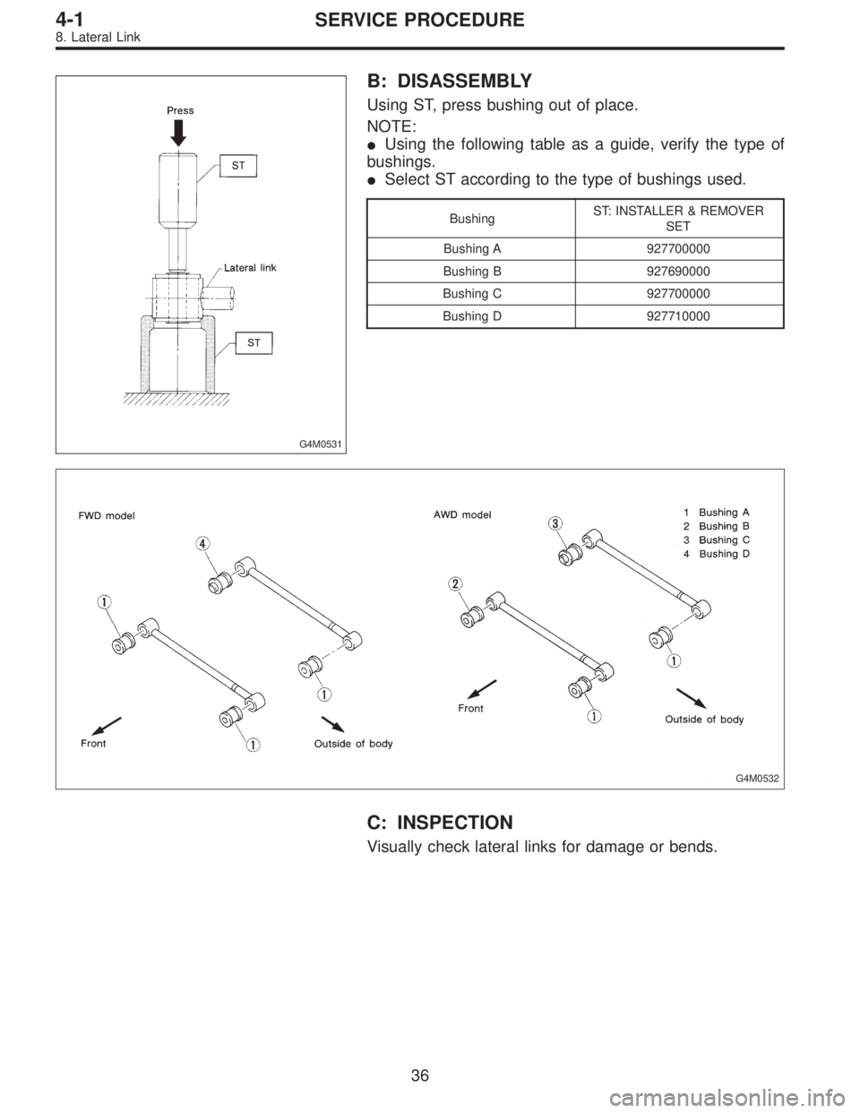
B: DISASSEMBLY
Using ST, press bushing out of place.
NOTE:
�Using the following table as a guide, verify the type of
bushings.
�Select ST according to the type of bushings used.
BushingST: INSTALLER & REMOVER
SET
Bushing A 927700000
Bushing B 927690000
Bushing C 927700000
Bushing D 927710000
G4M0532
C: INSPECTION
Visually check lateral links for damage or bends.
36
4-1SERVICE PROCEDURE
8. Lateral Link
Page 1116 of 3342
G4M0533
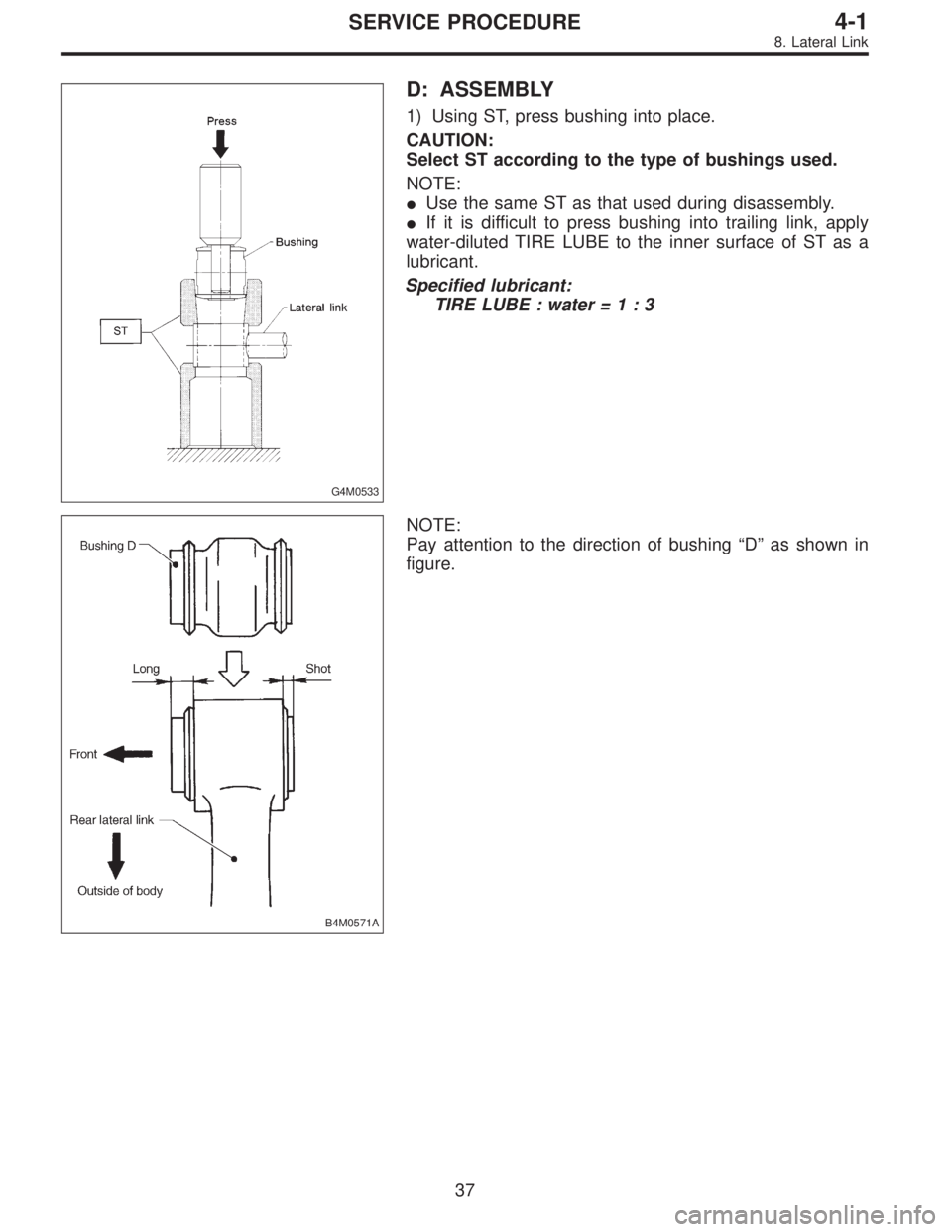
D: ASSEMBLY
1) Using ST, press bushing into place.
CAUTION:
Select ST according to the type of bushings used.
NOTE:
�Use the same ST as that used during disassembly.
�If it is difficult to press bushing into trailing link, apply
water-diluted TIRE LUBE to the inner surface of ST as a
lubricant.
Specified lubricant:
TIRE LUBE : water=1:3
B4M0571A
NOTE:
Pay attention to the direction of bushing“D”as shown in
figure.
37
4-1SERVICE PROCEDURE
8. Lateral Link
Page 1117 of 3342
B4M0197A
2) Press ST plunger until bushing flange protrudes beyond
lateral link.
NOTE:
Use the same ST as that used during disassembly.
B4M0198A
3) Turn lateral link upside down. Press ST plunger in the
opposite direction that outlined in step 2) until bushing is
correctly positioned in trailing link.
NOTE:
Use the same ST as that used during disassembly.
38
4-1SERVICE PROCEDURE
8. Lateral Link
Page 1126 of 3342
 Permanent distortion or breakage of coil spring Replace.
(2) Unsmooth operation of damper st")
1. Suspension
1. IMPROPER VEHICLE POSTURE OR IMPROPER
WHEEL ARCH HEIGHT
Possible causes Countermeasures
(1) Permanent distortion or breakage of coil spring Replace.
(2) Unsmooth operation of damper strut Replace.
(3) Installation of wrong strut Replace with proper parts.
(4) Installation of wrong coil spring Replace with proper parts.
2. POOR RIDE COMFORT
1) Large rebound shock
2) Rocking of vehicle continues too long after running over
bump and/or hump.
3) Large shock in bumping
Possible causes Countermeasures
(1) Breakage of coil spring Replace.
(2) Over-inflation pressure of tire Adjust.
(3) Improper wheel arch height Adjust or replace coil springs with new ones.
(4) Fault in operation of damper strut Replace.
(5) Damage or deformation of strut mount Replace.
(6) Unsuitability of maximum and/or minimum length of
damper strutReplace with proper parts.
(7) Deformation or loss of bushing Replace.
(8) Deformation or damage of helper in strut assembly Replace.
(9) Oil leakage of damper strut Replace.
3. NOISE
Possible causes Countermeasures
(1) Wear or damage of damper strut component parts Replace.
(2) Loosening of suspension link installing bolt and/or nut Retighten to the specified torque.
(3) Deformation or loss of bushing Replace.
(4) Unsuitability of maximum and/or minimum length of
damper strutReplace with proper parts.
(5) Breakage of coil spring Replace.
(6) Wear or damage of ball joint Replace.
(7) Deformation of stabilizer clamp Replace.
47
4-1DIAGNOSTICS
1. Suspension
 Remove nut (do not remove bolt.) securing transverse
link to crossmember.
4) Remove two bolts securing bushing bracket of trans-
verse link to vehicle body at rear bushing location.
G4M0493")
 Remove housing. Refer to“4-2 WHEELS AND AXLES”
f")

 Press ST plunger until bushing flange protrudes beyond
lateral link.
NOTE:
Use the same ST as that used during disassembly.
B4M0198A
3) Turn lateral link upside down. Press ST plunger in t")