Page 3155 of 3342

B: ON-BOARD DIAGNOSIS WITH SELECT
MONITOR
1. GENERAL
The on-board diagnosis function of the cruise control sys-
tem uses an external select monitor.
The on-board diagnosis function operates in two
categories, which are used depending on the type of prob-
lems;
�Cruise cancel conditions diagnosis
�Real-time diagnosis
Applicable cartridge No.: 498349601
�Cruise cancel conditions diagnosis
This category of diagnosis requires actual vehicle driv-
ing in order to determine the cause, (as when cruise
speed is cancelled during driving although cruise cancel
condition is not entered).
Cruise control module memory stores the cancel condi-
tion (Code No.) which occurred during driving. When
there are plural cancel conditions (Code No.), they are
shown in order, for 2 seconds per Code No., on the
select monitor.
CAUTION:
�The cruise control memory stores not only the
cruise“cancel”which occurred (although“cancel”
operation is not entered by the driver), but also the
“cancel”condition input by the driver.
�The content of memory is cleared when ignition
switch or cruise main switch is turned OFF.
�Real-time diagnosis
The real-time diagnosis function is used to determine
whether or not the input of output signal system is in good
order, according to signal emitted from switches, sensors,
etc.
Vehicle cannot be driven at cruise speed because prob-
lems occurs in the cruise control system or its associ-
ated circuits.
Monitor the signal conditions from switches and sen-
sors.
9
6-2BODY ELECTRICAL SYSTEM
6. Diagnostics Chart for On-board Diagnosis System
Page 3156 of 3342
 Connect select monitor.
2) Start the engine and turn cruise control main switch to
ON.
3) Set select monitor in“FB0”mode.
4) Drive vehicle at least 40 km/h")
2. CRUISE CANCEL CONDITIONS DIAGNOSIS
1) Connect select monitor.
2) Start the engine and turn cruise control main switch to
ON.
3) Set select monitor in“FB0”mode.
4) Drive vehicle at least 40 km/h (25 MPH) with cruise
speed set.
5) If cruise speed is canceled itself (without doing any
cancel operations), a trouble code will appear on select
monitor display.
CAUTION:
�A trouble code will also appear when cruise cancel
is effected by driver. Do not confuse.
�Have a co-worker ride in vehicle to assist in diagno-
sis during driving.
NOTE:
Trouble code will be cleared by turning ignition switch or
cruise control main switch to OFF.
3. REAL-TIME DIAGNOSIS
1) Connect select monitor.
2) Turn ignition switch and cruise control main switch to
ON.
3) Set select monitor in“FA 0”mode.
4) Ensure that normal indication is displayed when con-
trols are operated as indicated below:
�When SET/COAST switch is pressed.
�When RESUME/ACCEL switch is pressed.
�When brake pedal is depressed. (Stop and brake switch
turns ON.)
�When clutch pedal is depressed. (MT model)
�When select lever is set to N position. (AT model)
10
6-2BODY ELECTRICAL SYSTEM
6. Diagnostics Chart for On-board Diagnosis System
Page 3157 of 3342
7. Diagnostics Chart for Power Line
A: BASIC DIAGNOSTICS PROCEDURE
Drive at cruise speed.
Cruise speed can be set.
(Cruise control is available.)Cruise speed cannot be set.
(Cruise control is not available.)
Check cruise control main switch
light and circuit.
Check cruise control main
switch circuit.
OK
�Not OK
Repair.
Check cruise control main
switch.
OK
�Not OK
Repair.
Faulty cruise control module.
��
�
�
11
6-2BODY ELECTRICAL SYSTEM
7. Diagnostics Chart for Power Line
Page 3158 of 3342
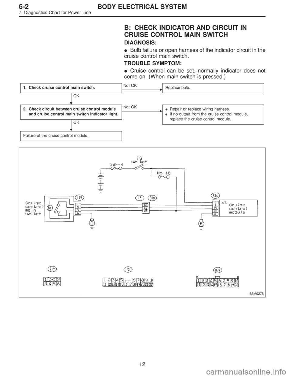
B: CHECK INDICATOR AND CIRCUIT IN
CRUISE CONTROL MAIN SWITCH
DIAGNOSIS:
�Bulb failure or open harness of the indicator circuit in the
cruise control main switch.
TROUBLE SYMPTOM:
�Cruise control can be set, normally indicator does not
come on. (When main switch is pressed.)
1. Check cruise control main switch.
OK
�Not OK
Replace bulb.
2. Check circuit between cruise control module
and cruise control main switch indicator light.
OK
�Not OK
�Repair or replace wiring harness.
�If no output from the cruise control module,
replace the cruise control module.
Failure of the cruise control module.
B6M0275
�
�
12
6-2BODY ELECTRICAL SYSTEM
7. Diagnostics Chart for Power Line
Page 3159 of 3342
B6M0180
1. CHECK CRUISE CONTROL MAIN SWITCH.
1) Remove cruise control main switch.
2) Measure resistance between cruise control main switch
terminals.
Terminals / Specified resistance:
No. 1—No. 6 / Approx. 50Ω
B6M0528A
B6M0531A
2. CHECK CIRCUIT BETWEEN CRUISE CONTROL
MODULE AND CRUISE CONTROL MAIN SWITCH
INDICATOR LIGHT.
1) Turn the ignition switch to ON.
2) Turn cruise control main switch to ON.
3) Measure voltage between cruise control main switch
connector and the body.
Connector & terminal / Specified voltage:
(i19) No. 1—Body / 10 V, or more
4) Turn the ignition switch and cruise control main switch
to OFF.
5) Remove the connector from the cruise control main
switch.
6) Measure resistance of ground circuit between the
cruise control main switch connector and body.
Connector & terminal / Specified resistance:
(i19) No. 6—Body / 10Ω, max.
13
6-2BODY ELECTRICAL SYSTEM
7. Diagnostics Chart for Power Line
Page 3160 of 3342
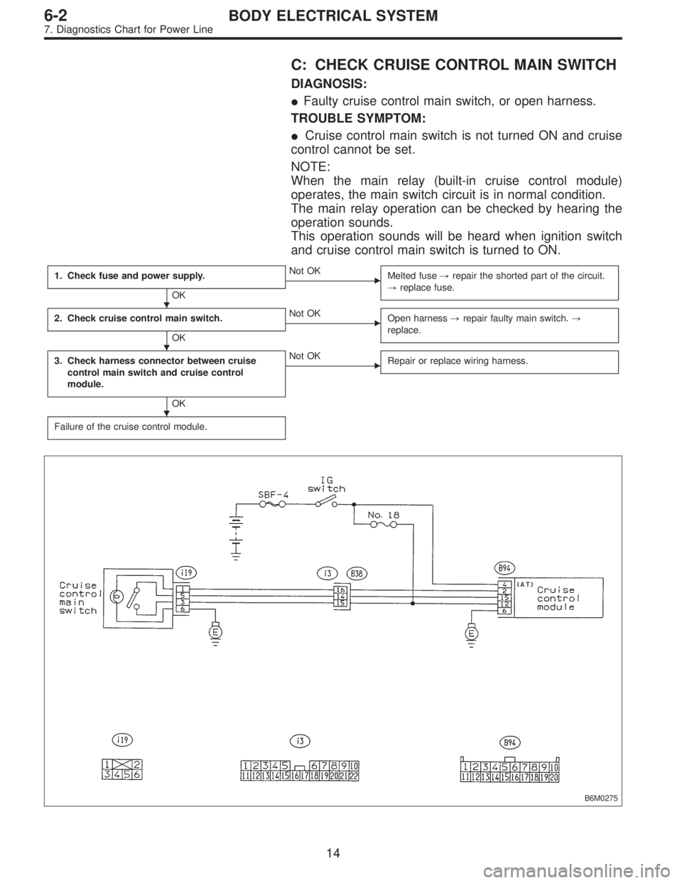
C: CHECK CRUISE CONTROL MAIN SWITCH
DIAGNOSIS:
�Faulty cruise control main switch, or open harness.
TROUBLE SYMPTOM:
�Cruise control main switch is not turned ON and cruise
control cannot be set.
NOTE:
When the main relay (built-in cruise control module)
operates, the main switch circuit is in normal condition.
The main relay operation can be checked by hearing the
operation sounds.
This operation sounds will be heard when ignition switch
and cruise control main switch is turned to ON.
1. Check fuse and power supply.
OK
�Not OK
Melted fuse,repair the shorted part of the circuit.
,replace fuse.
2. Check cruise control main switch.
OK
�Not OK
Open harness,repair faulty main switch.,
replace.
3. Check harness connector between cruise
control main switch and cruise control
module.
OK
�Not OK
Repair or replace wiring harness.
Failure of the cruise control module.
B6M0275
�
�
�
14
6-2BODY ELECTRICAL SYSTEM
7. Diagnostics Chart for Power Line
Page 3161 of 3342
 Check fuse No. 18.
2) Turn ignition switch to ON.
3) Measure voltage between fuse box connector and body.
Connector & terminal / Specified voltage:
(B51) No.")
G6M0181
1. CHECK FUSE AND POWER SUPPLY.
1) Check fuse No. 18.
2) Turn ignition switch to ON.
3) Measure voltage between fuse box connector and body.
Connector & terminal / Specified voltage:
(B51) No. 4—Body / 10 V, or more
B6M0183B
2. CHECK CRUISE CONTROL MAIN SWITCH.
1) Turn ignition switch to OFF.
2) Remove cruise control main switch and disconnect con-
nector.
3) Turn ignition switch to ON.
4) Measure voltage between cruise control main switch
connector and body.
Connector & terminal / Specified voltage:
(i19) No. 3—Body / 10 V, or more
G6M0244
5) Measure resistance between cruise control main switch
terminals.
Terminals / Specified resistance:
No. 3—No. 5 / 10Ω, max. (ON)
1MΩ, min. (OFF)
B6M0184B
3. CHECK HARNESS CONNECTOR BETWEEN
CRUISE CONTROL MAIN SWITCH AND CRUISE
CONTROL MODULE.
1) Connect connector.
2) Turn ignition switch to ON.
3) Turn cruise control main switch to ON.
4) Measure voltage between each terminal of cruise con-
trol main switch or cruise control module and body.
Connector & terminal / Specified voltage:
(i19) No. 3—Body / 10 V, or more
(i19) No. 5—Body / 10 V, or more
(B94) No. 15—Body / 10 V, or more
NOTE:
Depress cruise control main switch with fingers while mea-
suring (i19) No. 5—Body.
15
6-2BODY ELECTRICAL SYSTEM
7. Diagnostics Chart for Power Line
Page 3162 of 3342

8. Diagnostics Chart with Trouble Code
A: TROUBLE CODE
Trouble code Item Contents of diagnosis Page
10 OK Normal 18
11 BRAKE/ST/CL or N�Input signals from brake switch“OFF”, stop light
switch“ON”(Brake pedal is in depressed condi-
tion.)
�Input signals from clutch switch“OFF”, or inhibi-
tor switch is in“N”position.
[Clutch pedal is depressed (MT), or select lever
is set to N position (AT).]20
12 NOT SET SP Out of cruise speed range 22
13 LOW SP LIM Low-speed control limiter 22
14 CANCEL SW Input signal from cancel switch 26
15 NO MEMORY No memorized cruise speed—
21 SP SENS NG Faulty vehicle speed sensor 2 22
22 COM SW NGFaulty SET/COAST switch or RESUME/ACCEL
switch26
23 RELAY NG Faulty safety relay included in cruise control module 29
24 CPU RAM NG Faulty CPU RAM included in cruise control module 29
31 MOTOR NG Faulty vacuum motor or motor drive system 30
32 AIR VAL NG Faulty air valve or valve drive system 30
33 REL VAL NG Faulty release valve or valve drive system 30
16
6-2BODY ELECTRICAL SYSTEM
8. Diagnostics Chart with Trouble Code
Cruise speed cannot be set.
(Cruise control is not avai")
 Remove cruise control main switch.
2) Measure resistance between cruise control main switch
terminals.
Terminals / Specified resistance:
No. 1—No. 6 /")