Page 3172 of 3342
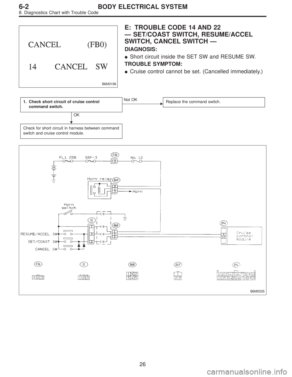
B6M0196
E: TROUBLE CODE 14 AND 22
—SET/COAST SWITCH, RESUME/ACCEL
SWITCH, CANCEL SWITCH—
DIAGNOSIS:
�Short circuit inside the SET SW and RESUME SW.
TROUBLE SYMPTOM:
�Cruise control cannot be set. (Cancelled immediately.)
1. Check short circuit of cruise control
command switch.
OK
�Not OK
Replace the command switch.
Check for short circuit in harness between command
switch and cruise control module.
B6M0535
�
26
6-2BODY ELECTRICAL SYSTEM
8. Diagnostics Chart with Trouble Code
Page 3173 of 3342
B6M0536
1. CHECK SHORT CIRCUIT OF CRUISE CONTROL
COMMAND SWITCH.
1) Turn ignition switch to ON.
2) Measure voltage between each terminal of connector
(S1).
Terminals / Specified resistance:
SET switch ON
(S1) No. 1—(S1) No.2/10—13 V
RESUME switch ON
(S1) No. 1—(S1) No.3/10—13 V
CANCEL switch ON
(S1) No. 1—(S1) No.2/10—13 V
(S1) No. 1—(S1) No.3/10—13 V
27
6-2BODY ELECTRICAL SYSTEM
8. Diagnostics Chart with Trouble Code
Page 3174 of 3342
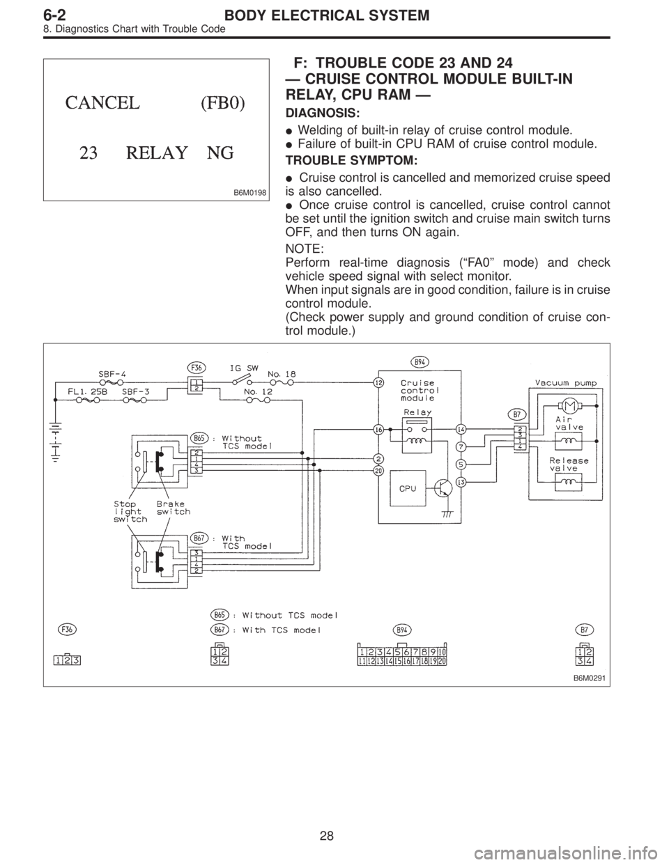
B6M0198
F: TROUBLE CODE 23 AND 24
—CRUISE CONTROL MODULE BUILT-IN
RELAY, CPU RAM—
DIAGNOSIS:
�Welding of built-in relay of cruise control module.
�Failure of built-in CPU RAM of cruise control module.
TROUBLE SYMPTOM:
�Cruise control is cancelled and memorized cruise speed
is also cancelled.
�Once cruise control is cancelled, cruise control cannot
be set until the ignition switch and cruise main switch turns
OFF, and then turns ON again.
NOTE:
Perform real-time diagnosis (“FA 0”mode) and check
vehicle speed signal with select monitor.
When input signals are in good condition, failure is in cruise
control module.
(Check power supply and ground condition of cruise con-
trol module.)
B6M0291
28
6-2BODY ELECTRICAL SYSTEM
8. Diagnostics Chart with Trouble Code
Page 3175 of 3342
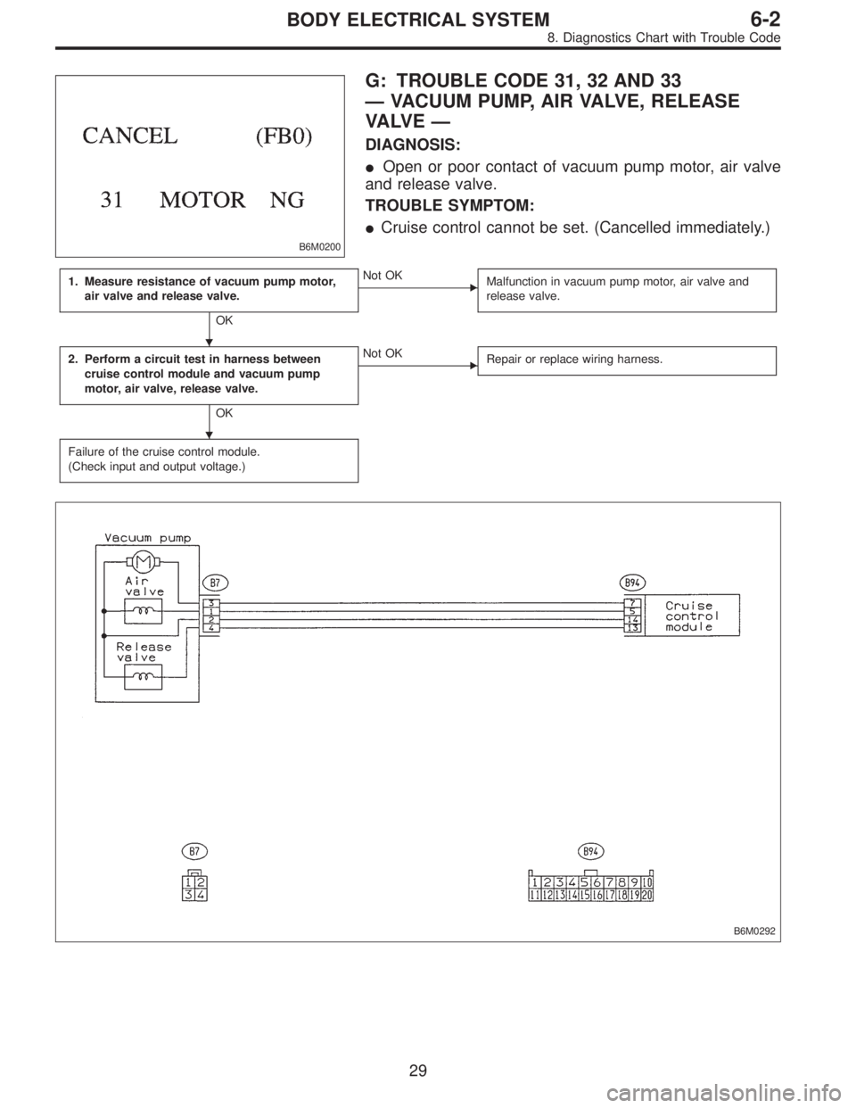
B6M0200
G: TROUBLE CODE 31, 32 AND 33
—VACUUM PUMP, AIR VALVE, RELEASE
VA LV E—
DIAGNOSIS:
�Open or poor contact of vacuum pump motor, air valve
and release valve.
TROUBLE SYMPTOM:
�Cruise control cannot be set. (Cancelled immediately.)
1. Measure resistance of vacuum pump motor,
air valve and release valve.
OK
�Not OK
Malfunction in vacuum pump motor, air valve and
release valve.
2. Perform a circuit test in harness between
cruise control module and vacuum pump
motor, air valve, release valve.
OK
�Not OK
Repair or replace wiring harness.
Failure of the cruise control module.
(Check input and output voltage.)
B6M0292
�
�
29
6-2BODY ELECTRICAL SYSTEM
8. Diagnostics Chart with Trouble Code
Page 3176 of 3342
B6M0271
1. MEASURE RESISTANCE OF VACUUM PUMP
MOTOR, AIR VALVE AND RELEASE VALVE.
1) Disconnect connector of vacuum pump and valve.
2) Measure resistance of vacuum pump motor, air valve
and release valve.
Terminals / Specified resistance:
No. 2—No. 3 / 46Ω(Vacuum pump motor)
No. 2—No. 1 / 69Ω(Air valve)
No. 2—No. 4 / 69Ω(Release valve)
B6M0293A
2. PERFORM A CIRCUIT TEST IN HARNESS
BETWEEN CRUISE CONTROL MODULE AND
VACUUM PUMP MOTOR, AIR VALVE, RELEASE
VA LV E .
1) Disconnect connectors from cruise control module,
vacuum pump and valve.
2) Measure resistance of harness connector between
cruise control module, vacuum pump motor, air valve and
release valve.
Connector & terminal / Specified resistance:
(B7) No. 1—(B94) No. 5 / 10Ω, max.
(B7) No. 2—(B94) No. 14 / 10Ω, max.
(B7) No. 3—(B94) No. 7 / 10Ω, max.
(B7) No. 4—(B94) No. 13 / 10Ω, max.
30
6-2BODY ELECTRICAL SYSTEM
8. Diagnostics Chart with Trouble Code
Page 3179 of 3342
B6M0205
D: MODE F03 AND F04
—MEMORIZED CRUISE SET SPEED (MSP)—
CONDITION:
Driving at minimum of 40 km/h (25 MPH) and set cruise
control.
SPECIFIED DATA:
Compare displayed vehicle speed on select monitor in
mode“F03”and“F04”with the speed in mode“F01”and
“F02”.
�F03: Memorized cruise set speed is indicated in mile
per hour (MPH).
�F04: Memorized cruise set speed is indicated in kilome-
ter per hour (km/h).
NOTE:
�F01: Actual vehicle speed is indicated in mile per hour
(MPH).
�F02: Actual vehicle speed is indicated in kilometer per
hour (km/h).
�Probable cause (Item outside“specified data”)
1. Cruise control module
�Check cruise control module input/output signals.
2. Cruise control command switch�Check cruise control command switch.
33
6-2BODY ELECTRICAL SYSTEM
9. Diagnostics Chart with Select Monitor
Page 3199 of 3342

MB-2 Power window circuit breaker
MB-3Engine control module
Fuel pump relay
Main relay
OBD-II service connector
MB-4 A/C relay holder
MB-5 He")
No. Load
MB-1Fuse holder (Rear power supply & seat
heater)
MB-2 Power window circuit breaker
MB-3Engine control module
Fuel pump relay
Main relay
OBD-II service connector
MB-4 A/C relay holder
MB-5 Headlight alarm relay (with security)
MB-6 Headlight LH
MB-7Daytime running light control module
Diode (Lighting)
Diode (Security)
Lighting switch
MB-8Combination meter
Front fog light switch
Headlight RH
Front fog light relay
MB-9Door lock timer
Headlight alarm relay
Interrupt relay
Radio
Security control module
Security indicator light
Spot light
Room light
Step light
Combination meter
Luggage room light
Trailer connector
Trunk room light
MB-10 A/C relay holder
SBF-6ABS relay box
TCS motor relay
SBF-7 TCS valve relay
ALT-1Combination meter
Daytime running light control module
Diode (TCS)
IG Headlight alarm relay
STCruise control module
Engine control module
Inhibitor switch (AT)
Interrupt relay
Starter interlock relay (MT)
FB-1Front washer motor
Rear washer motor
FB-2Engine control module
Main fan relay 1
FB-3Sub fan relay 2
Sub fan motor
FB-4Engine control module
Fuel pump relay
Ignition coil
Transmission control moduleNo. Load
FB-5 ABS relay box
FB-6Side marker light LH
Side marker light RH
FB-7 Door lock timer
FB-9 Hazard switch
FB-10AT shift lock control module
Key warning switch
Power antenna
FB-11 Radio
FB-12 Front accessory power supply
FB-13Mirror heater
Rear power supply relay
Remote control rearview mirror switch
Security control module
Vanity mirror illumination light
FB-14AT shift lock control module
Combination switch
Front wiper motor
Rear wiper motor
Rear wiper relay
FB-15ABS/TCS control module
Transmission control module
FB-16Rear defogger
Rear defogger condenser
Rear defogger switch
FB-17 Rear defogger switch
FB-18AT shift lock control module
Back-up light switch (MT)
Inhibitor switch (AT)
FB-19 Hazard switch
FB-20A/C switch
Combination meter
Mode control panel
TCS off switch
FB-22Blower motor relay
Check connector
Daytime running light control module
Daytime running light relay
FRESH/RECIRC actuator
Hi-beam relay
Power window and sunroof relay
Seat belt timer
FB-23 Airbag control module
FB-24 Airbag control module
FB-25 Lighting switch
20
6-3WIRING DIAGRAM
6. Wiring Diagram
Page 3200 of 3342
No. Load
FB-26 Parking switch
FB-27 Parking switch
FB-28 Illumination light
FB-29 Illumination light
FB-30Pedal stroke switch
Stop light switch
Stop & brake switch
FB-31 Horn relay
FB-32 Blower motor relay
FB-33 Parking switch
FB-34License plate light
Rear combination light LH
Rear combination light RH
Rear finisher light LH
Rear finisher light RH
FB-35ABS control module
ABS/TCS control module
TCS valve relay
Cruise control main switch
Cruise control module
FB-36 Front fog light relay
FB-37 Main fan relay 1
21
6-3WIRING DIAGRAM
6. Wiring Diagram
 Turn ignition switch to ON.
2) Measure voltage between each terminal of connector
(S1).
Terminals / Specified resistance:
SET switch")
 Disconnect connector of vacuum pump and valve.
2) Measure resistance of vacuum pump motor, air valve
and release val")
—
CONDITION:
Driving at minimum of 40 km/h (25 MPH) and set cruise
control.
SPECIFIED DATA:
Compare displayed vehicle speed on select m")
