Page 1474 of 3342

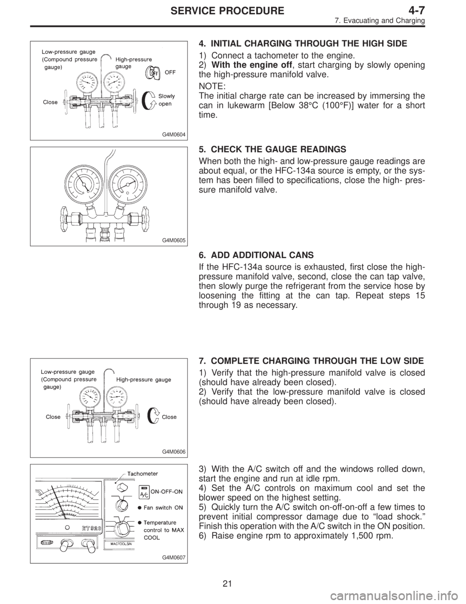
G4M0604
4. INITIAL CHARGING THROUGH THE HIGH SIDE
1) Connect a tachometer to the engine.
2)With the engine off, start charging by slowly opening
the high-pressure manifold valve.
NOTE:
The initial charge rate can be increased by immersing the
can in lukewarm [Below 38°C (100°F)] water for a short
time.
G4M0605
5. CHECK THE GAUGE READINGS
When both the high- and low-pressure gauge readings are
about equal, or the HFC-134a source is empty, or the sys-
tem has been filled to specifications, close the high- pres-
sure manifold valve.
6. ADD ADDITIONAL CANS
If the HFC-134a source is exhausted, first close the high-
pressure manifold valve, second, close the can tap valve,
then slowly purge the refrigerant from the service hose by
loosening the fitting at the can tap. Repeat steps 15
through 19 as necessary.
G4M0606
7. COMPLETE CHARGING THROUGH THE LOW SIDE
1) Verify that the high-pressure manifold valve is closed
(should have already been closed).
2) Verify that the low-pressure manifold valve is closed
(should have already been closed).
G4M0607
3) With the A/C switch off and the windows rolled down,
start the engine and run at idle rpm.
4) Set the A/C controls on maximum cool and set the
blower speed on the highest setting.
5) Quickly turn the A/C switch on-off-on-off a few times to
prevent initial compressor damage due to“load shock.”
Finish this operation with the A/C switch in the ON position.
6) Raise engine rpm to approximately 1,500 rpm.
21
4-7SERVICE PROCEDURE
7. Evacuating and Charging
Page 2086 of 3342

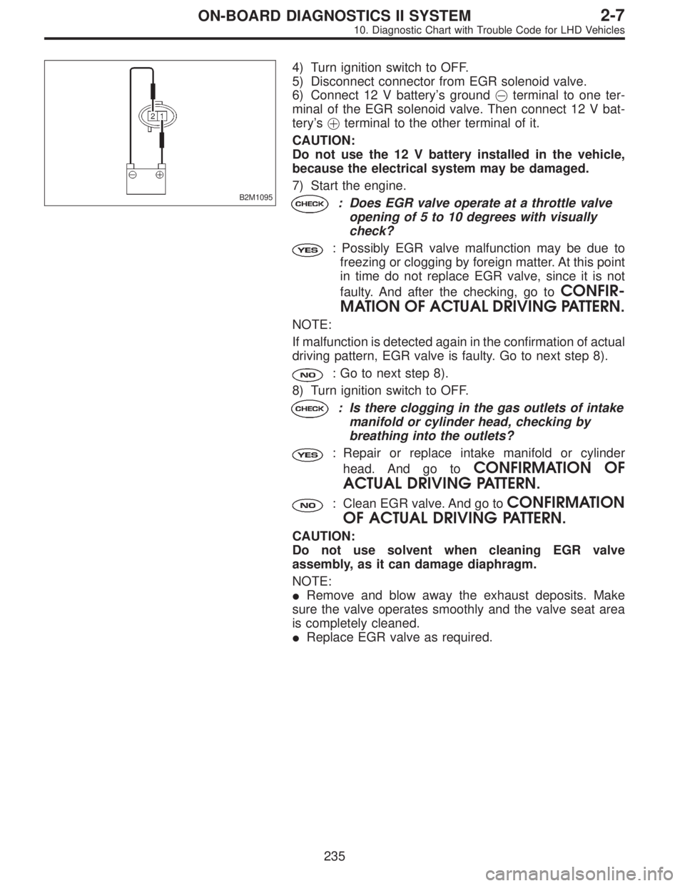
B2M1095
4) Turn ignition switch to OFF.
5) Disconnect connector from EGR solenoid valve.
6) Connect 12 V battery’s ground�terminal to one ter-
minal of the EGR solenoid valve. Then connect 12 V bat-
tery’s�terminal to the other terminal of it.
CAUTION:
Do not use the 12 V battery installed in the vehicle,
because the electrical system may be damaged.
7) Start the engine.
: Does EGR valve operate at a throttle valve
opening of 5 to 10 degrees with visually
check?
: Possibly EGR valve malfunction may be due to
freezing or clogging by foreign matter. At this point
in time do not replace EGR valve, since it is not
faulty. And after the checking, go to
CONFIR-
MATION OF ACTUAL DRIVING PATTERN.
NOTE:
If malfunction is detected again in the confirmation of actual
driving pattern, EGR valve is faulty. Go to next step 8).
: Go to next step 8).
8) Turn ignition switch to OFF.
: Is there clogging in the gas outlets of intake
manifold or cylinder head, checking by
breathing into the outlets?
: Repair or replace intake manifold or cylinder
head. And go to
CONFIRMATION OF
ACTUAL DRIVING PATTERN.
: Clean EGR valve. And go toCONFIRMATION
OF ACTUAL DRIVING PATTERN.
CAUTION:
Do not use solvent when cleaning EGR valve
assembly, as it can damage diaphragm.
NOTE:
�Remove and blow away the exhaust deposits. Make
sure the valve operates smoothly and the valve seat area
is completely cleaned.
�Replace EGR valve as required.
235
2-7ON-BOARD DIAGNOSTICS II SYSTEM
10. Diagnostic Chart with Trouble Code for LHD Vehicles
Page 2098 of 3342

10AS1CHECK DTC P0106, P0107, P0108, P0443,
P1102, P1122 OR P1422 ON DISPLAY.
: Does the Subaru select monitor or OBD-II
general scan tool indicate DTC P0106,
P0107, P0108, P0443, P1102, P1122 or
P1422?
: Inspect the relevant DTC P0106, P0107, P0108,
P0443, P1102, P1122 or P1422 using“10. Diag-
nostics Chart with Trouble Code”.
[T10A0].>
NOTE:
In this case, it is not necessary to inspect DTC P0441.
: Go to step10AS2.
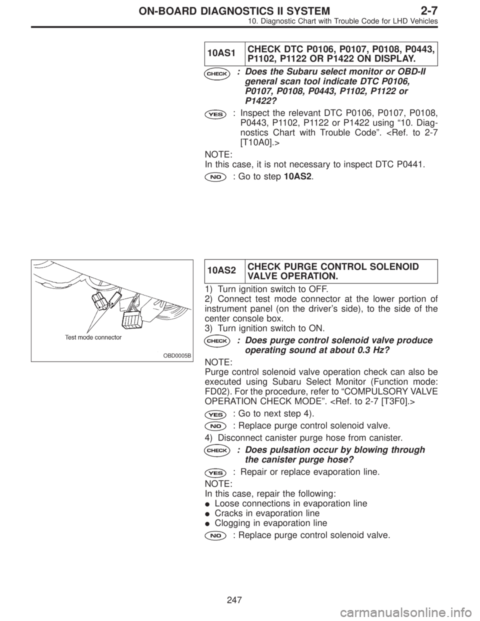
OBD0005B
10AS2CHECK PURGE CONTROL SOLENOID
VALVE OPERATION.
1) Turn ignition switch to OFF.
2) Connect test mode connector at the lower portion of
instrument panel (on the driver’s side), to the side of the
center console box.
3) Turn ignition switch to ON.
: Does purge control solenoid valve produce
operating sound at about 0.3 Hz?
NOTE:
Purge control solenoid valve operation check can also be
executed using Subaru Select Monitor (Function mode:
FD02). For the procedure, refer to“COMPULSORY VALVE
OPERATION CHECK MODE”.
: Go to next step 4).
: Replace purge control solenoid valve.
4) Disconnect canister purge hose from canister.
: Does pulsation occur by blowing through
the canister purge hose?
: Repair or replace evaporation line.
NOTE:
In this case, repair the following:
�Loose connections in evaporation line
�Cracks in evaporation line
�Clogging in evaporation line
: Replace purge control solenoid valve.
247
2-7ON-BOARD DIAGNOSTICS II SYSTEM
10. Diagnostic Chart with Trouble Code for LHD Vehicles
Page 3199 of 3342

No. Load
MB-1Fuse holder (Rear power supply & seat
heater)
MB-2 Power window circuit breaker
MB-3Engine control module
Fuel pump relay
Main relay
OBD-II service connector
MB-4 A/C relay holder
MB-5 Headlight alarm relay (with security)
MB-6 Headlight LH
MB-7Daytime running light control module
Diode (Lighting)
Diode (Security)
Lighting switch
MB-8Combination meter
Front fog light switch
Headlight RH
Front fog light relay
MB-9Door lock timer
Headlight alarm relay
Interrupt relay
Radio
Security control module
Security indicator light
Spot light
Room light
Step light
Combination meter
Luggage room light
Trailer connector
Trunk room light
MB-10 A/C relay holder
SBF-6ABS relay box
TCS motor relay
SBF-7 TCS valve relay
ALT-1Combination meter
Daytime running light control module
Diode (TCS)
IG Headlight alarm relay
STCruise control module
Engine control module
Inhibitor switch (AT)
Interrupt relay
Starter interlock relay (MT)
FB-1Front washer motor
Rear washer motor
FB-2Engine control module
Main fan relay 1
FB-3Sub fan relay 2
Sub fan motor
FB-4Engine control module
Fuel pump relay
Ignition coil
Transmission control moduleNo. Load
FB-5 ABS relay box
FB-6Side marker light LH
Side marker light RH
FB-7 Door lock timer
FB-9 Hazard switch
FB-10AT shift lock control module
Key warning switch
Power antenna
FB-11 Radio
FB-12 Front accessory power supply
FB-13Mirror heater
Rear power supply relay
Remote control rearview mirror switch
Security control module
Vanity mirror illumination light
FB-14AT shift lock control module
Combination switch
Front wiper motor
Rear wiper motor
Rear wiper relay
FB-15ABS/TCS control module
Transmission control module
FB-16Rear defogger
Rear defogger condenser
Rear defogger switch
FB-17 Rear defogger switch
FB-18AT shift lock control module
Back-up light switch (MT)
Inhibitor switch (AT)
FB-19 Hazard switch
FB-20A/C switch
Combination meter
Mode control panel
TCS off switch
FB-22Blower motor relay
Check connector
Daytime running light control module
Daytime running light relay
FRESH/RECIRC actuator
Hi-beam relay
Power window and sunroof relay
Seat belt timer
FB-23 Airbag control module
FB-24 Airbag control module
FB-25 Lighting switch
20
6-3WIRING DIAGRAM
6. Wiring Diagram