Page 3163 of 3342
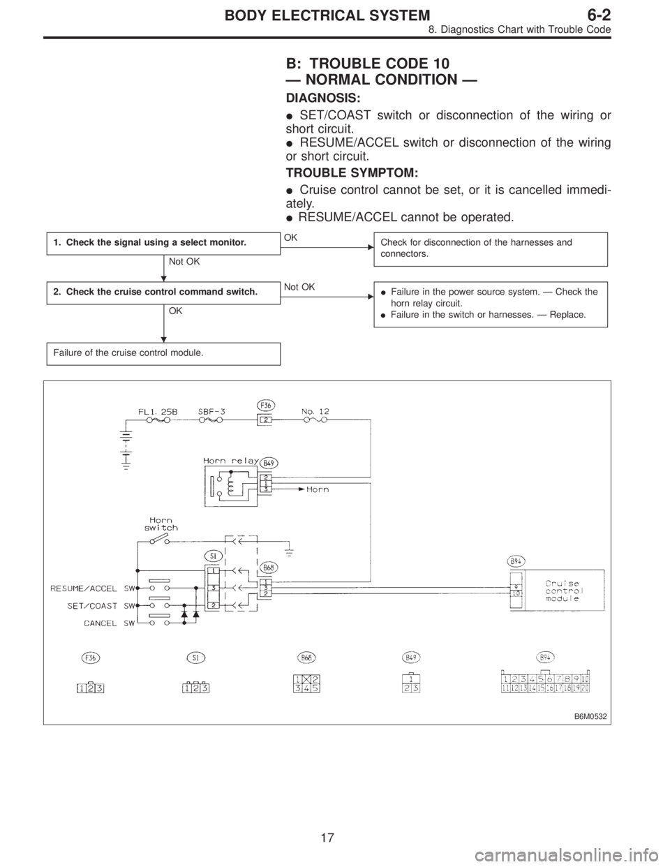
B: TROUBLE CODE 10
—NORMAL CONDITION—
DIAGNOSIS:
�SET/COAST switch or disconnection of the wiring or
short circuit.
�RESUME/ACCEL switch or disconnection of the wiring
or short circuit.
TROUBLE SYMPTOM:
�Cruise control cannot be set, or it is cancelled immedi-
ately.
�RESUME/ACCEL cannot be operated.
1. Check the signal using a select monitor.
Not OK
�OK
Check for disconnection of the harnesses and
connectors.
2. Check the cruise control command switch.
OK
�Not OK
�Failure in the power source system.—Check the
horn relay circuit.
�Failure in the switch or harnesses.—Replace.
Failure of the cruise control module.
B6M0532
�
�
17
6-2BODY ELECTRICAL SYSTEM
8. Diagnostics Chart with Trouble Code
Page 3164 of 3342
BR
5 Inhibitor switch (AT) N
6——
7——
8——
9——
10—�")
LED No. Signal name Display
1 SET/COAST switch SE
2 RESUME/ACCEL switch RE
3 Stop light switch ST
4�Brake switch
�Clutch switch (MT)BR
5 Inhibitor switch (AT) N
6——
7——
8——
9——
10——
SE RE ST BR N
—————
1
2345
678910
1. CHECK THE SIGNAL USING A SELECT MONITOR.
1) Turn ignition switch to ON.
2) Turn cruise control main switch to ON.
3) Set select monitor in“FA 0”mode.
4) Check signals for proper operation.
(1) When pushing the SET switch:
LED No. 1 goes out—lights.
(2) When pushing the RESUME switch:
LED No. 2 goes out—lights.
B6M0533
B6M0527
2. CHECK THE CRUISE CONTROL COMMAND
SWITCH.
1) Disconnect connector from command switch.
2) Measure voltage between connector (S1) and body.
Connector & terminal / Specified voltage:
(S1) No. 1—Body / 10 V, or more
3) Check for harness short circuit between command
switch and body.
Terminals / Specified resistance:
No. 2—Body / 1 MΩ, min.
No. 3—Body / 1 MΩ, min.
B6M0534
4) Measure resistance between each terminal of switch
side connector to check the switch operation.
Terminals:
No. 1—No. 2 (SET/COAST SWITCH)
No. 1—No. 3 (RESUME/ACCEL SWITCH)
Specified resistance:
10Ω, max. (ON)
1MΩ, min. (OFF)
18
6-2BODY ELECTRICAL SYSTEM
8. Diagnostics Chart with Trouble Code
Page 3165 of 3342
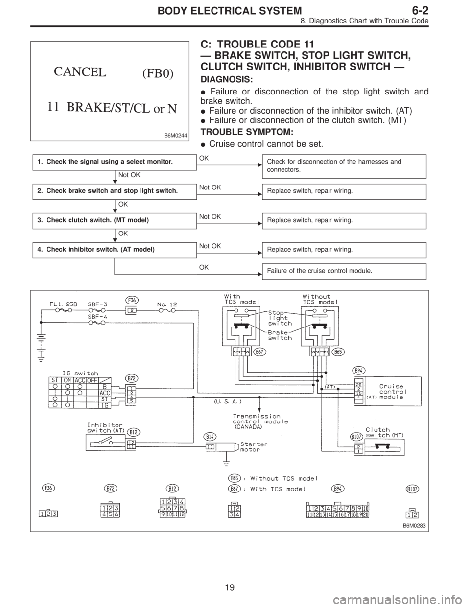
B6M0244
C: TROUBLE CODE 11
—BRAKE SWITCH, STOP LIGHT SWITCH,
CLUTCH SWITCH, INHIBITOR SWITCH—
DIAGNOSIS:
�Failure or disconnection of the stop light switch and
brake switch.
�Failure or disconnection of the inhibitor switch. (AT)
�Failure or disconnection of the clutch switch. (MT)
TROUBLE SYMPTOM:
�Cruise control cannot be set.
1. Check the signal using a select monitor.
Not OK
�OK
Check for disconnection of the harnesses and
connectors.
2. Check brake switch and stop light switch.
OK
�Not OK
Replace switch, repair wiring.
3. Check clutch switch. (MT model)
OK
�Not OK
Replace switch, repair wiring.
4. Check inhibitor switch. (AT model)�Not OK
Replace switch, repair wiring.
�OK
Failure of the cruise control module.
B6M0283
�
�
�
19
6-2BODY ELECTRICAL SYSTEM
8. Diagnostics Chart with Trouble Code
Page 3166 of 3342
BR
5 Inhibitor switch (AT) N
6——
7——
8——
9——
10—�")
LED No. Signal name Display
1 SET/COAST switch SE
2 RESUME/ACCEL switch RE
3 Stop light switch ST
4�Brake switch
�Clutch switch (MT)BR
5 Inhibitor switch (AT) N
6——
7——
8——
9——
10——
SE RE ST BR N
—————
1
2345
678910
1. CHECK THE SIGNAL USING A SELECT MONITOR.
1) Turn ignition switch to ON.
2) Turn cruise control main switch to ON.
3) Apply parking brake securely.
4) Set select monitor in“FA 0”mode.
5) Release the clutch pedal. (MT model)
6) Depress the brake pedal and check signals for proper
operation.
Stop light switch: LED No. 3 goes out—lights.
Brake switch : LED No. 4 goes out—lights.
7) Release the brake pedal.
8) Depress the clutch pedal and check signal for proper
operation. (MT model)
Clutch switch: LED No. 4 goes out—lights.
9) Set the selector lever from D to N position and check
signal for proper operation. (AT model)
Inhibitor switch: LED No. 5 goes out—lights.
G6M0183
2. CHECK BRAKE SWITCH AND STOP LIGHT
SWITCH.
1) Remove connector of stop and brake switch.
2) Check circuit between each terminal.
Pedal operationBrake switch between
No. 1—No. 4Stop light switch between
No. 2—No. 3
Depressing the
brake pedal.1MΩ,ormore 1Ω, or less
Without
depressing the
brake pedal.1Ω, or less 1 MΩ,ormore
G6M0184
3. CHECK CLUTCH SWITCH. (MT MODEL)
1) Disconnect connector from clutch switch.
2) Check continuity of the clutch switch.
Terminals / Specified resistance:
No. 1—No. 2 / 10Ω, max. (Without pedal
depressing.)
/1MΩ, min. (Pedal depressing.)
20
6-2BODY ELECTRICAL SYSTEM
8. Diagnostics Chart with Trouble Code
Page 3168 of 3342
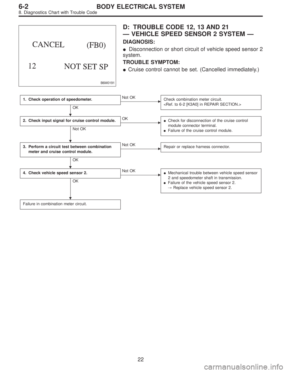
B6M0191
D: TROUBLE CODE 12, 13 AND 21
—VEHICLE SPEED SENSOR 2 SYSTEM—
DIAGNOSIS:
�Disconnection or short circuit of vehicle speed sensor 2
system.
TROUBLE SYMPTOM:
�Cruise control cannot be set. (Cancelled immediately.)
1. Check operation of speedometer.
OK
�Not OK
Check combination meter circuit.
2. Check input signal for cruise control module.
Not OK
�OK
�Check for disconnection of the cruise control
module connector terminal.
�Failure of the cruise control module.
3. Perform a circuit test between combination
meter and cruise control module.
OK
�Not OK
Repair or replace harness connector.
4. Check vehicle speed sensor 2.
OK
�Not OK
�Mechanical trouble between vehicle speed sensor
2 and speedometer shaft in transmission.
�Failure of the vehicle speed sensor 2.
,Replace vehicle speed sensor 2.
Failure in combination meter circuit.
�
�
�
�
22
6-2BODY ELECTRICAL SYSTEM
8. Diagnostics Chart with Trouble Code
Page 3169 of 3342
B6M0285
1. CHECK OPERATION OF SPEEDOMETER.
Make sure that speedometer indicates the vehicle speed
by driving the vehicle.
B6M0247B
2. CHECK INPUT SIGNAL FOR CRUISE CONTROL
MODULE.
WARNING:
Be careful not to be caught up by the running wheels.
1) Set the vehicle on free roller, or lift-up the vehicle and
support with safety stands.
2) Set oscilloscope to cruise control module connector ter-
minals.
Connector & terminal / (B94) No. 19—Body
23
6-2BODY ELECTRICAL SYSTEM
8. Diagnostics Chart with Trouble Code
Page 3170 of 3342
 Start the engine.
4) Shift on the gear position, and keep the vehicle speed
at constant.
5) Measure signal voltage.
Specified voltage (V): 2 V, or more
NOTE:
�If the vehicle speed i")
G2M0931
B6M0287
3) Start the engine.
4) Shift on the gear position, and keep the vehicle speed
at constant.
5) Measure signal voltage.
Specified voltage (V): 2 V, or more
NOTE:
�If the vehicle speed increases, the width of amplitude
(W) decreases.
�If oscilloscope is not available, check input signal
(vehicle speed signal) by using a select monitor. (Refer to
the procedure as described below.)
�Using the select monitor:
(1) Set the vehicle on free roller, or lift-up the vehicle and
support with safety stands.
(2) Turn ignition switch to OFF and set select monitor.
(3) Turn ignition switch to ON.
(4) Turn cruise control main switch to ON.
(5) Set select monitor in“F01”or“F02”mode.
(6) Drive the vehicle at speed greater than 40 km/h (25
MPH).
(7) Check that vehicle speed indication on select moni-
tor and speedometer are equal.
NOTE:
�When there is a disconnection or short circuit in the har-
ness between the meter and the cruise control module, the
indicated value will be 0 to 1.0 km/h (0 to 0.6 MPH).
�In“F01”mode, vehicle speed is indicated in mile per
hour (MPH).
In“F02”mode, vehicle speed is indicated in kilometer per
hour (km/h).
B3M0250
3. PERFORM A CIRCUIT TEST BETWEEN
COMBINATION METER AND CRUISE CONTROL
MODULE.
1) Turn ignition switch to OFF.
2) Remove combination meter.
B6M0194B
3) Disconnect connector from cruise control module.
4) Measure resistance of harness connector between
combination meter and cruise control module.
Connector & terminal / Specified resistance:
(i10) No. 10—(B94) No. 19 / 10Ω, max.
24
6-2BODY ELECTRICAL SYSTEM
8. Diagnostics Chart with Trouble Code
Page 3171 of 3342
 Measure resistance of harness connector between
cruise control module and body to make sure that circuit
does not short.
Connector & terminal / Specified resistance:
(B94) No. 19—Body /")
B6M0248B
5) Measure resistance of harness connector between
cruise control module and body to make sure that circuit
does not short.
Connector & terminal / Specified resistance:
(B94) No. 19—Body / 1 MΩ, min.
B3M0289
4. CHECK VEHICLE SPEED SENSOR 2.
1) Disconnect connector from vehicle speed sensor 2.
2) Measure resistance between terminals of vehicle speed
sensor 2.
Terminals / Specified resistance:
No. 1—No. 2 / 350—450Ω
B3M0256
WARNING:
Be careful not to be caught up by the running wheels.
3) Set the vehicle on free roller, or lift-up the vehicle and
support with safety stands.
4) Drive the vehicle at speed greater than 20 km/h (12
MPH).
5) Measure voltage between terminals of vehicle speed
sensor 2.
Terminals / Specified voltage:
No. 1—No. 2 / 2 V, or more (AC range)
B3M0257
�Using an oscilloscope:
(1) Turn ignition switch to OFF.
(2) Set oscilloscope to vehicle speed sensor 2.
(3) Drive the vehicle at speed greater than 20 km/h (12
MPH).
(4) Measure signal voltage.
Specified voltage (V): 5 V, min.
B3M0254A
25
6-2BODY ELECTRICAL SYSTEM
8. Diagnostics Chart with Trouble Code