Page 295 of 3342
5. Camshaft
A: REMOVAL
1. RELATED PARTS
1) Remove timing belt, camshaft sprockets and related
parts.
2) Remove valve rocker assembly.
2. CAMSHAFT LH
B2M0384A
1) Remove oil level gauge guide attaching bolt.
2) Remove camshaft support LH.
CAUTION:
Do not damage the camshaft position sensor.
3) Remove O-ring.
4) Remove camshaft LH.
5) Remove oil seal.
CAUTION:
�Do not remove oil seal unless necessary.
�Do not scratch journal surface when removing oil
seal.
33
2-3SERVICE PROCEDURE
5. Camshaft
Page 298 of 3342
C: INSTALLATION
1. CAMSHAFT LH
B2M0384B
Tightening torque: N⋅m (kg-m, ft-lb)
T1: 10 (1.0, 7)
T2: 16 (1.6, 12)
1) Apply a coat of engine oil to camshaft journals and
install camshaft LH.
2) Apply a coat of engine oil or grease to O-ring.
3) Install O-ring to camshaft support.
CAUTION:
Use a new O-ring.
4) Install camshaft support.
G2M0141
5) Apply a coat of grease to oil seal lips and install oil seal
on camshaft support by using ST1 and ST2.
CAUTION:
Use a new oil seal.
ST1 499597000 OIL SEAL GUIDE
ST2 499587100 OIL SEAL INSTALLER
6) Install oil level gauge guide bolt.
36
2-3SERVICE PROCEDURE
5. Camshaft
Page 302 of 3342
2. CYLINDER HEAD
B2M0119A
1) Remove timing belt, camshaft sprocket and related
parts.
2) Remove oil level gauge guide attaching bolt (left hand
only) and oil level gauge guide.
B2M0120A
3) Remove cylinder head bolts in numerical sequence
shown in Figure.
CAUTION:
Leave bolts�
1and�3engaged by three or four threads
to prevent cylinder head from falling.
4) While tapping cylinder head with a plastic hammer,
separate it from cylinder block.
Remove bolts�
1and�3to remove cylinder head.
5) Remove cylinder head gasket.
CAUTION:
Do not scratch the mating surface of cylinder head and
cylinder block.
6) Similarly, remove right side cylinder head.
39
2-3SERVICE PROCEDURE
6. Cylinder Head
Page 312 of 3342
(7) Further tighten all bolts by 80 to 90°in numerical
sequence.
CAUTION:
Ensure that the total“re-tightening angle”[steps (6)
and (7) above] do not exceed 180°.
3) Install oil level gauge guide attaching bolt (left side
only).
4) Install timing belt, camshaft sprocket and related parts.
2. INTAKE MANIFOLD
CAUTION:
Use dry compressed air to remove foreign particles
before installing each solenoid valve and sensor.
1) Install engine coolant pipe.
2) Install intake manifold.
3) Remove ENGINE STAND (ST).
49
2-3SERVICE PROCEDURE
6. Cylinder Head
Page 378 of 3342
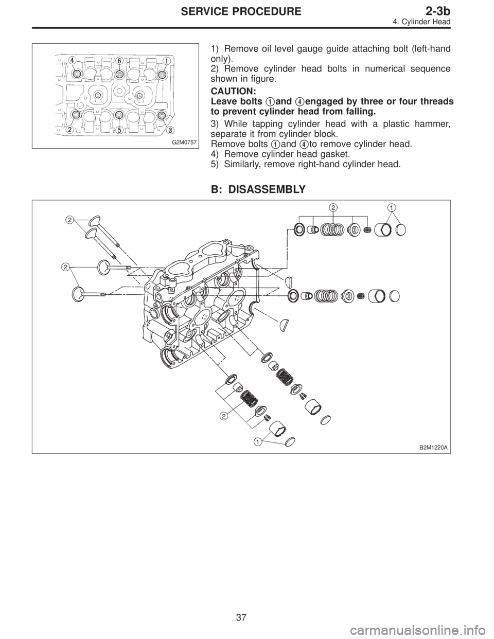
G2M0757
1) Remove oil level gauge guide attaching bolt (left-hand
only).
2) Remove cylinder head bolts in numerical sequence
shown in figure.
CAUTION:
Leave bolts�
1and�4engaged by three or four threads
to prevent cylinder head from falling.
3) While tapping cylinder head with a plastic hammer,
separate it from cylinder block.
Remove bolts�
1and�4to remove cylinder head.
4) Remove cylinder head gasket.
5) Similarly, remove right-hand cylinder head.
B: DISASSEMBLY
B2M1220A
37
2-3bSERVICE PROCEDURE
4. Cylinder Head
Page 387 of 3342
(7) Further tighten all bolts by 80 to 90°in numerical
sequence.
CAUTION:
Ensure that the total“re-tightening angle”[steps (6)
and (7) above] do not exceed 180°.
3) Install oil level gauge guide attaching bolt (left side
only).
2. INTAKE MANIFOLD
1) Install camshafts, rocker cover and related parts.
G2M0750
Tightening torque: N⋅m (kg-m, ft-lb)
T1: 10±0.7 (1.0±0.07, 7.2±0.5)
T2: 20±2 (2.0±0.2, 14.5±1.4)
46
2-3bSERVICE PROCEDURE
4. Cylinder Head
Page 424 of 3342
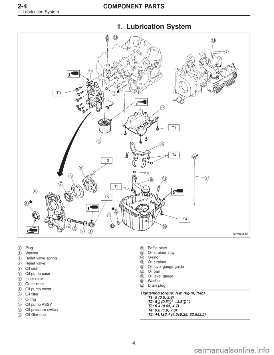
1. Lubrication System
B2M0314A
�1Plug
�
2Washer
�
3Relief valve spring
�
4Relief valve
�
5Oil seal
�
6Oil pump case
�
7Inner rotor
�
8Outer rotor
�
9Oil pump cover
�
10Oil filter
�
11O-ring
�
12Oil pump ASSY
�
13Oil pressure switch
�
14Oil filler duct�
15Baffle plate
�
16Oil strainer stay
�
17O-ring
�
18Oil strainer
�
19Oil level gauge guide
�
20Oil pan
�
21Oil level gauge
�
22Washer
�
23Drain plug
Tightening torque: N⋅m (kg-m, ft-lb)
T1: 5 (0.5, 3.6)
T2: 5
+1
�0(0.5+0.1
�0, 3.6+0.7
�0)
T3: 6.4 (0.65, 4.7)
T4: 9.8 (1.0, 7.0)
T5: 44.1±3.4 (4.5±0.35, 32.5±2.5)
4
2-4COMPONENT PARTS
1. Lubrication System
Page 434 of 3342
B2M0724
13) Connect connector to front oxygen sensor.
B2M0725
14) Connect connector to rear oxygen sensor. (California
2200 cc model only)
G2M0302
15) Install pitching stopper.
Tightening torque:
T1: 49±5 N⋅m (5.0±0.5 kg-m, 36.2±3.6 ft-lb)
T2: 57±10 N⋅m (5.8±1.0 kg-m, 42±7 ft-lb)
B2M0320
16) Install radiator upper brackets.
Tightening torque:
12±3 N⋅m (1.2±0.3 kg-m, 8.7±2.2 ft-lb)
B2M0321
17) Install air intake duct.
18) Fill engine oil through filler pipe up to upper point of
level gauge.
Engine oil capacity:
2200 cc ; Upper level
4.0�(4.2 US qt, 3.5 Imp qt)
Lower level
3.0�(3.2 US qt, 2.6 Imp qt)
2500 cc ; Upper level
4.5�(4.8 US qt, 4.0 Imp qt)
14
2-4SERVICE PROCEDURE
2. Oil Pan and Oil Strainer
![SUBARU LEGACY 1997 Service Repair Manual 5. Camshaft
A: REMOVAL
1. RELATED PARTS
1) Remove timing belt, camshaft sprockets and related
parts.
<Ref. to 2-3 [W3A0].>
2) Remove valve rocker assembly.
<Ref. to 2-3 [W4A0].>
2. CAMSHAFT LH
B2M0384](/manual-img/17/57434/w960_57434-294.png "SUBARU LEGACY 1997 Service Repair Manual 5. Camshaft
A: REMOVAL
1. RELATED PARTS
1) Remove timing belt, camshaft sprockets and related
parts.
<Ref. to 2-3 [W3A0].>
2) Remove valve rocker assembly.
<Ref. to 2-3 [W4A0].>
2. CAMSHAFT LH
B2M0384")

T1: 10 (1.0, 7)
T2: 16 (1.6, 12)
1) Apply a coat of engine oil to camshaft journals and
install camshaft LH.
2) Apply a c")
![SUBARU LEGACY 1997 Service Repair Manual 2. CYLINDER HEAD
B2M0119A
1) Remove timing belt, camshaft sprocket and related
parts.
<Ref. to 2-3 [W3A0].>
2) Remove oil level gauge guide attaching bolt (left hand
only) and oil level gauge guide.
B](/manual-img/17/57434/w960_57434-301.png "SUBARU LEGACY 1997 Service Repair Manual 2. CYLINDER HEAD
B2M0119A
1) Remove timing belt, camshaft sprocket and related
parts.
<Ref. to 2-3 [W3A0].>
2) Remove oil level gauge guide attaching bolt (left hand
only) and oil level gauge guide.
B")
![SUBARU LEGACY 1997 Service Repair Manual (7) Further tighten all bolts by 80 to 90°in numerical
sequence.
CAUTION:
Ensure that the total“re-tightening angle”[steps (6)
and (7) above] do not exceed 180°.
3) Install oil level gauge guide](/manual-img/17/57434/w960_57434-311.png "SUBARU LEGACY 1997 Service Repair Manual (7) Further tighten all bolts by 80 to 90°in numerical
sequence.
CAUTION:
Ensure that the total“re-tightening angle”[steps (6)
and (7) above] do not exceed 180°.
3) Install oil level gauge guide")
![SUBARU LEGACY 1997 Service Repair Manual (7) Further tighten all bolts by 80 to 90°in numerical
sequence.
CAUTION:
Ensure that the total“re-tightening angle”[steps (6)
and (7) above] do not exceed 180°.
3) Install oil level gauge guide](/manual-img/17/57434/w960_57434-386.png "SUBARU LEGACY 1997 Service Repair Manual (7) Further tighten all bolts by 80 to 90°in numerical
sequence.
CAUTION:
Ensure that the total“re-tightening angle”[steps (6)
and (7) above] do not exceed 180°.
3) Install oil level gauge guide")
 Connect connector to front oxygen sensor.
B2M0725
14) Connect connector to rear oxygen sensor. (California
2200 cc model only)
G2M0302
15) Install pitching stopper.
Tightening torque:
T1:")