Page 253 of 3342
G2M0093
4) Connect oil pressure gauge hose to cylinder block.
5) Start the engine, and measure oil pressure.
Oil pressure:
98 kPa (1.0 kg/cm
2,14 psi) or more at 800 rpm
294 kPa (3.0 kg/cm2, 43 psi) or more at 5,000 rpm
CAUTION:
�If oil pressure is out of specification, check oil
pump, oil filter and lubrication line.
�If oil pressure warning light is turned ON and oil
pressure is in specification, replace oil pressure
switch.
NOTE:
The specified data is based on an engine oil temperature
of 80°C (176°F).
6) After measuring oil pressure, install oil pressure switch.
Tightening torque:
25±3 N⋅m (2.5±0.3 kg-m, 18.1±2.2 ft-lb)
7) Install generator and V-belt in the reverse order of
removal, and adjust the V-belt deflection.
8
2-2
6. Engine Oil Pressure
Page 315 of 3342
G2M0163
7) Removal of oil pan
(1) Turn cylinder block with #2 and #4 piston sides
facing upward.
(2) Remove bolts which secure oil pan to cylinder
block.
(3) Insert a oil pan cutter blade between cylinder block-
to-oil pan clearance and remove oil pan.
CAUTION:
Do not use a screwdriver or similar tool in place of oil-
pan cutter.
8) Remove oil strainer stay.
9) Remove oil strainer.
10) Remove baffle plate.
11) Remove oil filter.
B: DISASSEMBLY
1. PISTON PIN AND CYLINDER BLOCK
CONNECTING BOLT
G2M0164
52
2-3SERVICE PROCEDURE
7. Cylinder Block
Page 337 of 3342
B2M0390A
(2) Apply fluid packing to matching surface of oil pump.
Fluid packing:
THREE BOND 1215 or equivalent
(3) Install oil pump on cylinder block. Be careful not to
damage oil seal during installation.
CAUTION:
�Do not forget to install O-ring and seal when install-
ing oil pump.
�Align flat surface of oil pump’s inner rotor with
crankshaft before installation.
G2M0628
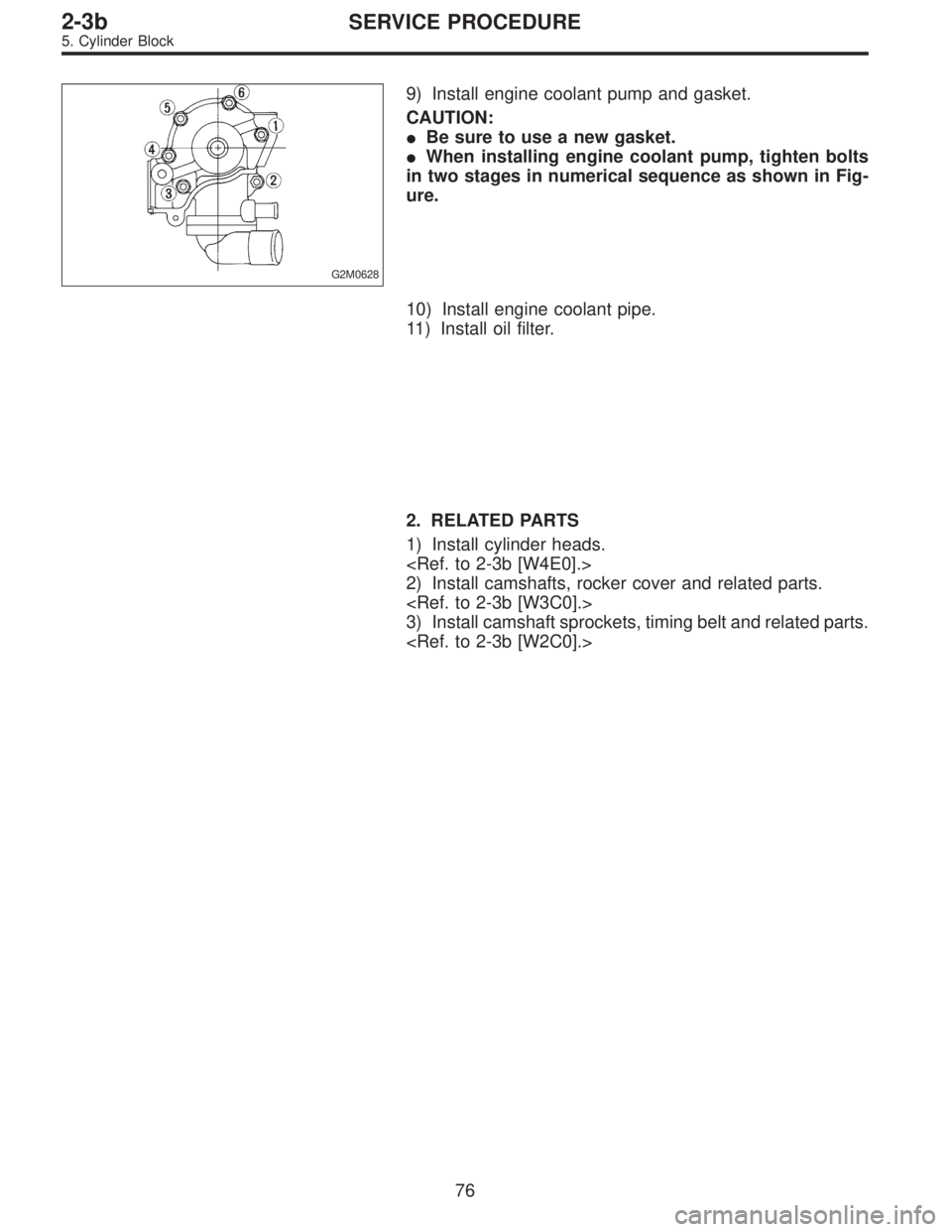
9) Install engine coolant pump and gasket.
CAUTION:
�Be sure to use a new gasket.
�When installing engine coolant pump, tighten bolts
in two stages in numerical sequence as shown in Fig-
ure.
10) Install engine coolant pipe.
11) Install oil filter.
2. RELATED PARTS
1) Install cylinder head and intake manifold.
2) Install timing belt, camshaft sprocket and related parts.
74
2-3SERVICE PROCEDURE
7. Cylinder Block
Page 340 of 3342
TROUBLE
Engine will not start.
Rough idle and engine stall
Low output, hesitation and poor acceleration
Surging
Engine does not return to idle.
Dieseling (Run-on)
After burning in exhaust system
Knocking
Excessive engine oil consumption
Excessive fuel consumption Starter does not turn.
Initial combustion does not occur.
Initial combustion occurs.
Engine stalls after initial combustion.
LUBRICATION SYSTEM
22 3 3�Incorrect oil pressure
2�Loosened oil pump attaching bolts and defective
gasket
2�Defective oil filter seal
2�Defective crankshaft oil seal
32�Defective rocker cover gasket
2�Loosened oil drain plug or defective gasket
2�Loosened oil pan fitting bolts or defective oil pan
COOLING SYSTEM
33221�Overheating
333�Over cooling
OTHERS
113 3�Malfunction of Evaporative Emission Control
System
21�Stuck or damaged throttle valve
322 2�Accelerator cable out of adjustment
77
2-3DIAGNOSTICS
1. Engine Trouble in General
Page 394 of 3342
B2M0706A
2) Remove drive plate.
To lock crankshaft use ST.
ST 498497100 CRANKSHAFT STOPPER
3) Remove oil separator cover.
4) Remove engine coolant pipe.
5) Remove engine coolant pump.
G2M0162
6) Remove oil pump from cylinder block.
Use a flat-bladed screwdriver as shown in Figure when
removing oil pump.
CAUTION:
Be careful not to scratch the mating surface of cylin-
der block and oil pump.
G2M0163
7) Removal of oil pan
(1) Turn cylinder block with #2 and #4 piston sides
facing upward.
(2) Remove bolts which secure oil pan to cylinder
block.
(3) Insert a oil pan cutter blade between cylinder block-
to-oil pan clearance and remove oil pan.
CAUTION:
Do not use a screwdriver or similar tool in place of oil-
pan cutter.
8) Remove oil strainer stay.
9) Remove oil strainer.
10) Remove baffle plate.
11) Remove oil filter.
53
2-3bSERVICE PROCEDURE
5. Cylinder Block
Page 417 of 3342
G2M0628
9) Install engine coolant pump and gasket.
CAUTION:
�Be sure to use a new gasket.
�When installing engine coolant pump, tighten bolts
in two stages in numerical sequence as shown in Fig-
ure.
10) Install engine coolant pipe.
11) Install oil filter.
2. RELATED PARTS
1) Install cylinder heads.
2) Install camshafts, rocker cover and related parts.
3) Install camshaft sprockets, timing belt and related parts.
76
2-3bSERVICE PROCEDURE
5. Cylinder Block
Page 420 of 3342
TROUBLE
Engine will not start.
Rough idle and engine stall
Low output, hesitation and poor acceleration
Surging
Engine does not return to idle.
Dieseling (Run-on)
After burning in exhaust system
Knocking
Excessive engine oil consumption
Excessive fuel consumption Starter does not turn.
Initial combustion does not occur.
Initial combustion occurs.
Engine stalls after initial combustion.
LUBRICATION SYSTEM
22 3 3�Incorrect oil pressure
2�Loosened oil pump attaching bolts and defective
gasket
2�Defective oil filter seal
2�Defective crankshaft oil seal
32�Defective rocker cover gasket
2�Loosened oil drain plug or defective gasket
2�Loosened oil pan fitting bolts or defective oil pan
COOLING SYSTEM
33221�Overheating
333�Over cooling
OTHERS
113 3�Malfunction of Evaporative Emission Control
System
21�Stuck or damaged throttle valve
322 2�Accelerator cable out of adjustment
79
2-3bDIAGNOSTICS
1. Engine Trouble in General
Page 422 of 3342

1. Lubrication System
A: SPECIFICATIONS
1. 2200 cc MODEL
Lubrication methodForced lubrication
Oil pumpPump typeTrochoid type
Number of teethInner rotor 9
Outer rotor 10
Outer rotor diameter x thickness 78x9mm(3.07 x 0.35 in)
Tip clearance between inner and outer rotorSTANDARD 0.04 — 0.14 mm (0.0016 — 0.0055 in)
LIMIT 0.18 mm (0.0071 in)
Side clearance between inner rotor and pump
caseSTANDARD 0.02 — 0.07 mm (0.0008 — 0.0028 in)
LIMIT 0.15 mm (0.0059 in)
Case clearance between outer rotor and pump
caseSTANDARD 0.10 — 0.175 mm (0.0039 — 0.0069 in)
LIMIT 0.20 mm (0.0079 in)
Capacity at
80°C (176°F)700 rpm Discharge- pressure 98 kPa (1.0 kg/cm
2, 14 psi) or more
- quantity 4.2�(4.4 US qt, 3.7 Imp qt)/min.
5,000 rpm Discharge- pressure 294 kPa (3.0 kg/cm
2, 43 psi) or more
- quantity 42.0�(11.10 US gal, 9.24 Imp gal)/min.
Relief valve operation pressure 490 kPa (5.0 kg/cm
2, 71 psi)
Oil filterTypeFull-flow filter type
Filtration area 1,000 cm
2(155 sq in)
By-pass valve opening pressure 157 kPa (1.6 kg/cm
2, 23 psi)
Outer diameter x width 80 x 70 mm (3.15 x 2.76 in)
Oil filter to engine thread size M 20 x 1.5
Relief valve (on rocker shaft) operation pressure 69 kPa (0.7kg/cm
2, 10 psi)
Oil pressure
switchTypeImmersed contact point type
Working voltage — wattage 12 V — 3.4 W or less
Warning light activation pressure 14.7 kPa (0.15 kg/cm
2, 2.1 psi)
Proof pressure More than 981 kPa (10 kg/cm
2, 142 psi)
Oil pan capacity4.0�(4.2 US qt, 3.5 Imp qt)
2
2-4SPECIFICATIONS AND SERVICE DATA
1. Lubrication System
 Connect oil pressure gauge hose to cylinder block.
5) Start the engine, and measure oil pressure.
Oil pressure:
98 kPa (1.0 kg/cm
2,14 psi) or more at 800 rpm
294 kPa (3.0 kg/cm2, 43 psi) o")
 Removal of oil pan
(1) Turn cylinder block with #2 and #4 piston sides
facing upward.
(2) Remove bolts which secure oil pan to cylinder
block.
(3) Insert a oil pan cutter blade between cyli")
 Apply fluid packing to matching surface of oil pump.
Fluid packing:
THREE BOND 1215 or equivalent
(3) Install oil pump on cylinder block. Be careful not to
damage oil seal during installa")

After burning in exhaust system
Knock")
 Remove drive plate.
To lock crankshaft use ST.
ST 498497100 CRANKSHAFT STOPPER
3) Remove oil separator cover.
4) Remove engine coolant pipe.
5) Remove engine coolant pump.
G2M0162
6) Remov")

After burning in exhaust system
Knock")