Page 864 of 3342
G3M0371
5) Remove the snap ring. Then remove the speedometer
driven gear.
G3M0372
6) Remove vehicle speed sensor 2.
7) Tap out the speedometer shaft to the outside of the
case, and remove the oil seal.
G3M0373
5. EXTENSION SECTION
1) Take out the transfer clutch by lightly tapping the end of
the rear drive shaft.
CAUTION:
Be careful not to damage the oil seal in the extension.
G3M0867
2) Remove duty solenoid C, transfer valve body and the
transfer pipe.
CAUTION:
�Take out the inlet filter.
�Do not damage the O-ring.
�Be careful not to bend the pipe.
B3M0831A
3) Take out the roller bearing inner race with ST.
ST 398527700 PULLER
4) Take out the roller bearing outer race with ST.
NOTE:
Hook ST in the inner side of the roller bearing outer race.
ST 398527700 PULLER
58
3-2SERVICE PROCEDURE
4. Overall Transmission
Page 882 of 3342

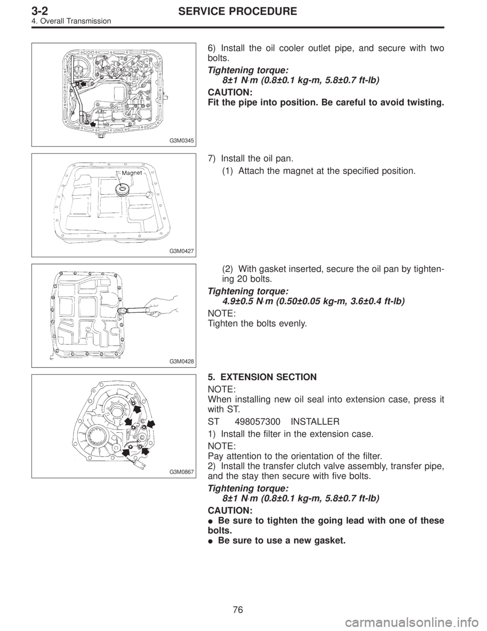
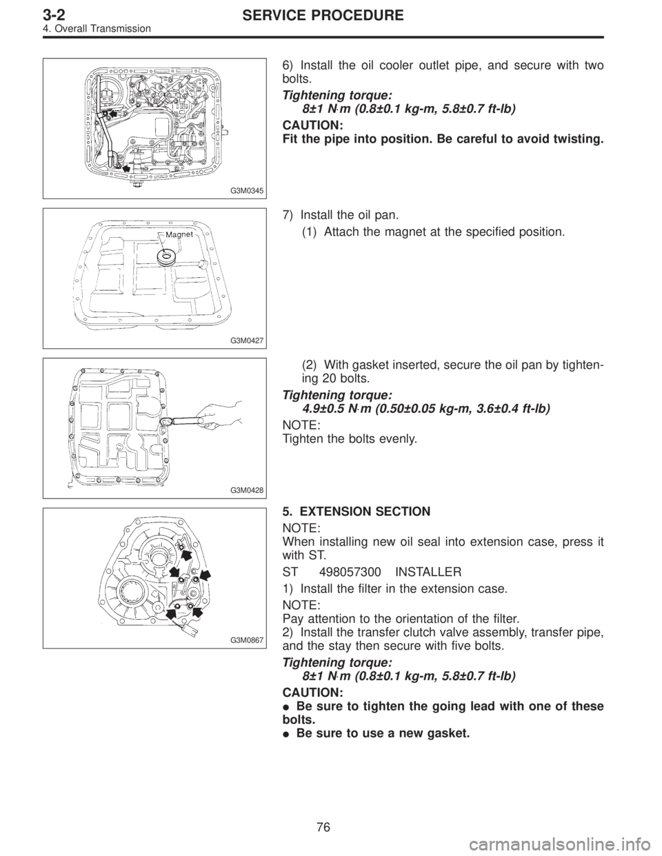
G3M0345
6) Install the oil cooler outlet pipe, and secure with two
bolts.
Tightening torque:
8±1 N⋅m (0.8±0.1 kg-m, 5.8±0.7 ft-lb)
CAUTION:
Fit the pipe into position. Be careful to avoid twisting.
G3M0427
7) Install the oil pan.
(1) Attach the magnet at the specified position.
G3M0428
(2) With gasket inserted, secure the oil pan by tighten-
ing 20 bolts.
Tightening torque:
4.9±0.5 N⋅m (0.50±0.05 kg-m, 3.6±0.4 ft-lb)
NOTE:
Tighten the bolts evenly.
G3M0867
5. EXTENSION SECTION
NOTE:
When installing new oil seal into extension case, press it
with ST.
ST 498057300 INSTALLER
1) Install the filter in the extension case.
NOTE:
Pay attention to the orientation of the filter.
2) Install the transfer clutch valve assembly, transfer pipe,
and the stay then secure with five bolts.
Tightening torque:
8±1 N⋅m (0.8±0.1 kg-m, 5.8±0.7 ft-lb)
CAUTION:
�Be sure to tighten the going lead with one of these
bolts.
�Be sure to use a new gasket.
76
3-2SERVICE PROCEDURE
4. Overall Transmission
Page 895 of 3342
G3M0906
5) Temporarily assemble lower valve body to upper valve
body.
CAUTION:
Be careful not to drop the upper body interior steel
ball, or the lower body interior filter, orifice check
spring, or orifice check valve.
B3M0406A
6) Install the duty solenoid B and the four brackets.
7) Tighten twenty seven bolts & washers and two reamer
bolts.
Tightening torque:
T1: 8±1 N⋅m (0.8±0.1 kg-m, 5.8±0.7 ft-lb)
T2: 11.3±1.5 N⋅m (1.15±0.15 kg-m, 8.3±1.1 ft-lb)
Unit: mm (in)
abcde
Length 70 (2.76) 50 (1.97) 33 (1.30) 27 (1.06) 28 (1.10)
Numbers 2 6 16 1 2
G3M0864
8) Install the shift solenoid and duty solenoid A.
a length : 16 mm (0.63 in)
b length : 27 mm (1.06 in)
Tightening torque:
8±1 N⋅m (0.8±0.1 kg-m, 5.8±0.7 ft-lb)
G3M0445
7. Oil Pump Assembly
A: DISASSEMBLY
1) Remove the oil seal retainer.
Also remove the O-ring and oil seal (air breather).
89
3-2SERVICE PROCEDURE
6. Control Valve Body - 7. Oil Pump Assembly
Page 926 of 3342
10. Transfer and Extension
B3M0375A
�1Snap ring
�
2Pressure plate
�
3Drive plate
�
4Driven plate
�
5Thrust needle bearing
�
6Snap ring
�
7Spring retainer
�
8Lathe cut seal ring
�
9Transfer clutch piston
�
10Lathe cut seal ring
�
11Needle bearing
�
12Rear drive shaft
�
13Ball bearing�
14Seal ring
�
15Vehicle speed sensor 1 (AWD only)
�
16Transfer clutch pipe
�
17Duty sol. C (Transfer clutch)
�
18Gasket
�
19Plate
�
20Filter
�
21Gasket
�
22Roller bearing
�
23Extension case
�
24Oil seal
�
25Dust seal
�
26Seal transfer piston�
27O-ring
�
28Test plug
�
29O-ring
�
30Clip
�
31Transfer valve body
�
32Clip
�
33Stay
Tightening torque: N⋅m (kg-m, ft-lb)
T1: 7±1 (0.7±0.1, 5.1±0.7)
T2: 8±1 (0.8±0.1, 5.8±0.7)
T3: 13±1 (1.3±0.1, 9.4±0.7)
T4: 25±2 (2.5±0.2, 18.1±1.4)
20
3-2COMPONENT PARTS
10. Transfer and Extension
Page 964 of 3342
G3M0371
5) Remove the snap ring. Then remove the speedometer
driven gear.
G3M0372
6) Remove vehicle speed sensor 2.
7) Tap out the speedometer shaft to the outside of the
case, and remove the oil seal.
G3M0373
5. EXTENSION SECTION
1) Take out the transfer clutch by lightly tapping the end of
the rear drive shaft.
CAUTION:
Be careful not to damage the oil seal in the extension.
G3M0867
2) Remove duty solenoid C, transfer valve body and the
transfer pipe.
CAUTION:
�Take out the inlet filter.
�Do not damage the O-ring.
�Be careful not to bend the pipe.
B3M0831A
3) Take out the roller bearing inner race with ST.
ST 398527700 PULLER
4) Take out the roller bearing outer race with ST.
NOTE:
Hook ST in the inner side of the roller bearing outer race.
ST 398527700 PULLER
58
3-2SERVICE PROCEDURE
4. Overall Transmission
Page 982 of 3342

G3M0345
6) Install the oil cooler outlet pipe, and secure with two
bolts.
Tightening torque:
8±1 N⋅m (0.8±0.1 kg-m, 5.8±0.7 ft-lb)
CAUTION:
Fit the pipe into position. Be careful to avoid twisting.
G3M0427
7) Install the oil pan.
(1) Attach the magnet at the specified position.
G3M0428
(2) With gasket inserted, secure the oil pan by tighten-
ing 20 bolts.
Tightening torque:
4.9±0.5 N⋅m (0.50±0.05 kg-m, 3.6±0.4 ft-lb)
NOTE:
Tighten the bolts evenly.
G3M0867
5. EXTENSION SECTION
NOTE:
When installing new oil seal into extension case, press it
with ST.
ST 498057300 INSTALLER
1) Install the filter in the extension case.
NOTE:
Pay attention to the orientation of the filter.
2) Install the transfer clutch valve assembly, transfer pipe,
and the stay then secure with five bolts.
Tightening torque:
8±1 N⋅m (0.8±0.1 kg-m, 5.8±0.7 ft-lb)
CAUTION:
�Be sure to tighten the going lead with one of these
bolts.
�Be sure to use a new gasket.
76
3-2SERVICE PROCEDURE
4. Overall Transmission
Page 995 of 3342
G3M0906
5) Temporarily assemble lower valve body to upper valve
body.
CAUTION:
Be careful not to drop the upper body interior steel
ball, or the lower body interior filter, orifice check
spring, or orifice check valve.
B3M0406A
6) Install the duty solenoid B and the four brackets.
7) Tighten twenty seven bolts & washers and two reamer
bolts.
Tightening torque:
T1: 8±1 N⋅m (0.8±0.1 kg-m, 5.8±0.7 ft-lb)
T2: 11.3±1.5 N⋅m (1.15±0.15 kg-m, 8.3±1.1 ft-lb)
Unit: mm (in)
abcde
Length 70 (2.76) 50 (1.97) 33 (1.30) 27 (1.06) 28 (1.10)
Numbers 2 6 16 1 2
G3M0864
8) Install the shift solenoid and duty solenoid A.
a length : 16 mm (0.63 in)
b length : 27 mm (1.06 in)
Tightening torque:
8±1 N⋅m (0.8±0.1 kg-m, 5.8±0.7 ft-lb)
G3M0445
7. Oil Pump Assembly
A: DISASSEMBLY
1) Remove the oil seal retainer.
Also remove the O-ring and oil seal (air breather).
89
3-2SERVICE PROCEDURE
6. Control Valve Body - 7. Oil Pump Assembly
Page 996 of 3342
G3M0906
5) Temporarily assemble lower valve body to upper valve
body.
CAUTION:
Be careful not to drop the upper body interior steel
ball, or the lower body interior filter, orifice check
spring, or orifice check valve.
B3M0406A
6) Install the duty solenoid B and the four brackets.
7) Tighten twenty seven bolts & washers and two reamer
bolts.
Tightening torque:
T1: 8±1 N⋅m (0.8±0.1 kg-m, 5.8±0.7 ft-lb)
T2: 11.3±1.5 N⋅m (1.15±0.15 kg-m, 8.3±1.1 ft-lb)
Unit: mm (in)
abcde
Length 70 (2.76) 50 (1.97) 33 (1.30) 27 (1.06) 28 (1.10)
Numbers 2 6 16 1 2
G3M0864
8) Install the shift solenoid and duty solenoid A.
a length : 16 mm (0.63 in)
b length : 27 mm (1.06 in)
Tightening torque:
8±1 N⋅m (0.8±0.1 kg-m, 5.8±0.7 ft-lb)
G3M0445
7. Oil Pump Assembly
A: DISASSEMBLY
1) Remove the oil seal retainer.
Also remove the O-ring and oil seal (air breather).
89
3-2SERVICE PROCEDURE
6. Control Valve Body - 7. Oil Pump Assembly