Page 1476 of 3342

8. Leak Testing
The following points should be kept in mind when conduct-
ing a refrigerant leak test.
1) The A/C system to be tested must have an adequate
refrigerant charge to begin with.
2) The area where the leak test is conducted must be free
of wind and drafts, with still air being the ideal condition.
3) The atmosphere where the leak test is conducted must
be free of refrigerant contamination.
4) Operate the A/C system for approx. 10 minutes, then
turn the engine off an begin the leak test.
5) Refrigerant gas is heavier than air, therefore always
hold the probe below the connection being tested.
6) When checking for a leak along a length of hose or
tube, the leak detector probe must be moved slowly,
approx. 25 mm (1 in) per second making sure probe does
not come in contact with the component being tested.
7) When checking for a leak at a certain point, the leak
detector probe must be held at that point for at least 5
seconds.
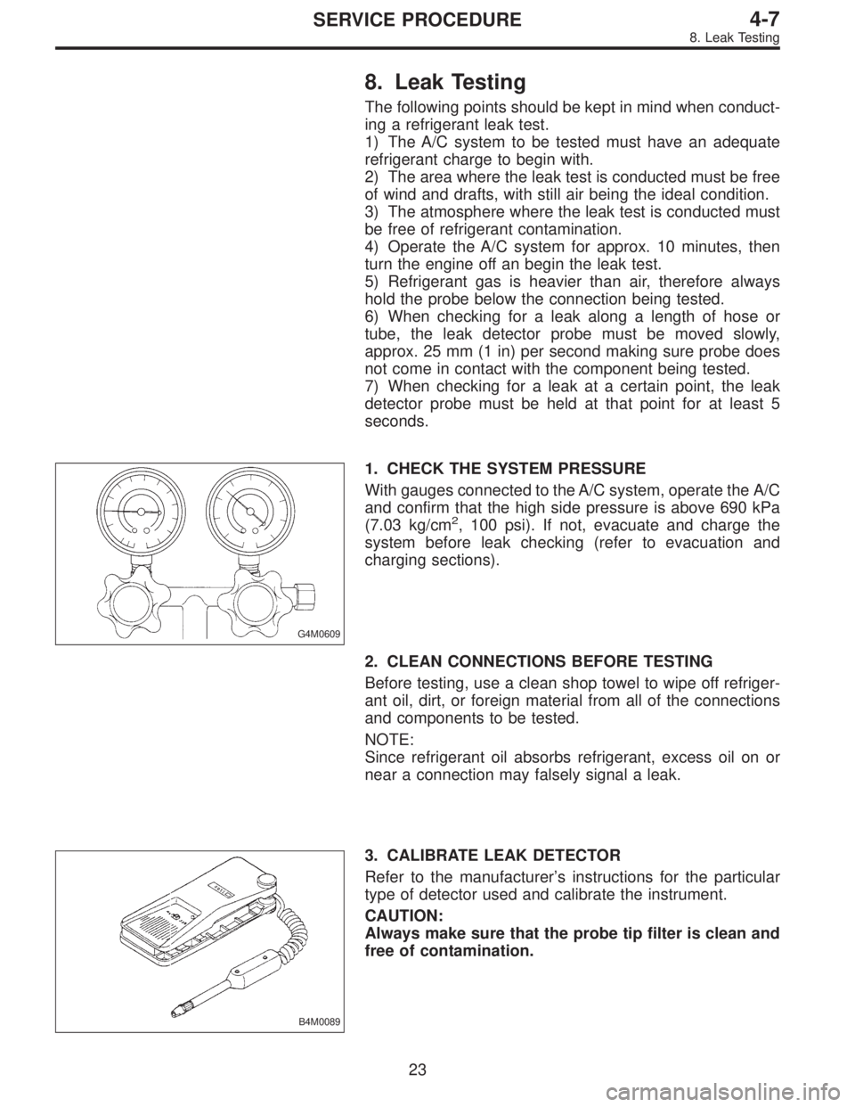
G4M0609
1. CHECK THE SYSTEM PRESSURE
With gauges connected to the A/C system, operate the A/C
and confirm that the high side pressure is above 690 kPa
(7.03 kg/cm
2, 100 psi). If not, evacuate and charge the
system before leak checking (refer to evacuation and
charging sections).
2. CLEAN CONNECTIONS BEFORE TESTING
Before testing, use a clean shop towel to wipe off refriger-
ant oil, dirt, or foreign material from all of the connections
and components to be tested.
NOTE:
Since refrigerant oil absorbs refrigerant, excess oil on or
near a connection may falsely signal a leak.
B4M0089
3. CALIBRATE LEAK DETECTOR
Refer to the manufacturer’s instructions for the particular
type of detector used and calibrate the instrument.
CAUTION:
Always make sure that the probe tip filter is clean and
free of contamination.
23
4-7SERVICE PROCEDURE
8. Leak Testing
Page 1856 of 3342

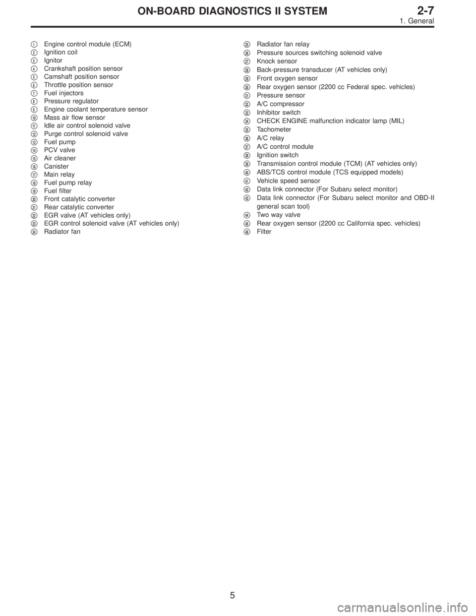
�1Engine control module (ECM)
�
2Ignition coil
�
3Ignitor
�
4Crankshaft position sensor
�
5Camshaft position sensor
�
6Throttle position sensor
�
7Fuel injectors
�
8Pressure regulator
�
9Engine coolant temperature sensor
�
10Mass air flow sensor
�
11Idle air control solenoid valve
�
12Purge control solenoid valve
�
13Fuel pump
�
14PCV valve
�
15Air cleaner
�
16Canister
�
17Main relay
�
18Fuel pump relay
�
19Fuel filter
�
20Front catalytic converter
�
21Rear catalytic converter
�
22EGR valve (AT vehicles only)
�
23EGR control solenoid valve (AT vehicles only)
�
24Radiator fan�
25Radiator fan relay
�
26Pressure sources switching solenoid valve
�
27Knock sensor
�
28Back-pressure transducer (AT vehicles only)
�
29Front oxygen sensor
�
30Rear oxygen sensor (2200 cc Federal spec. vehicles)
�
31Pressure sensor
�
32A/C compressor
�
33Inhibitor switch
�
34CHECK ENGINE malfunction indicator lamp (MIL)
�
35Tachometer
�
36A/C relay
�
37A/C control module
�
38Ignition switch
�
39Transmission control module (TCM) (AT vehicles only)
�
40ABS/TCS control module (TCS equipped models)
�
41Vehicle speed sensor
�
42Data link connector (For Subaru select monitor)
�
43Data link connector (For Subaru select monitor and OBD-II
general scan tool)
�
44Two way valve
�
45Rear oxygen sensor (2200 cc California spec. vehicles)
�
46Filter
5
2-7ON-BOARD DIAGNOSTICS II SYSTEM
1. General
Page 1858 of 3342

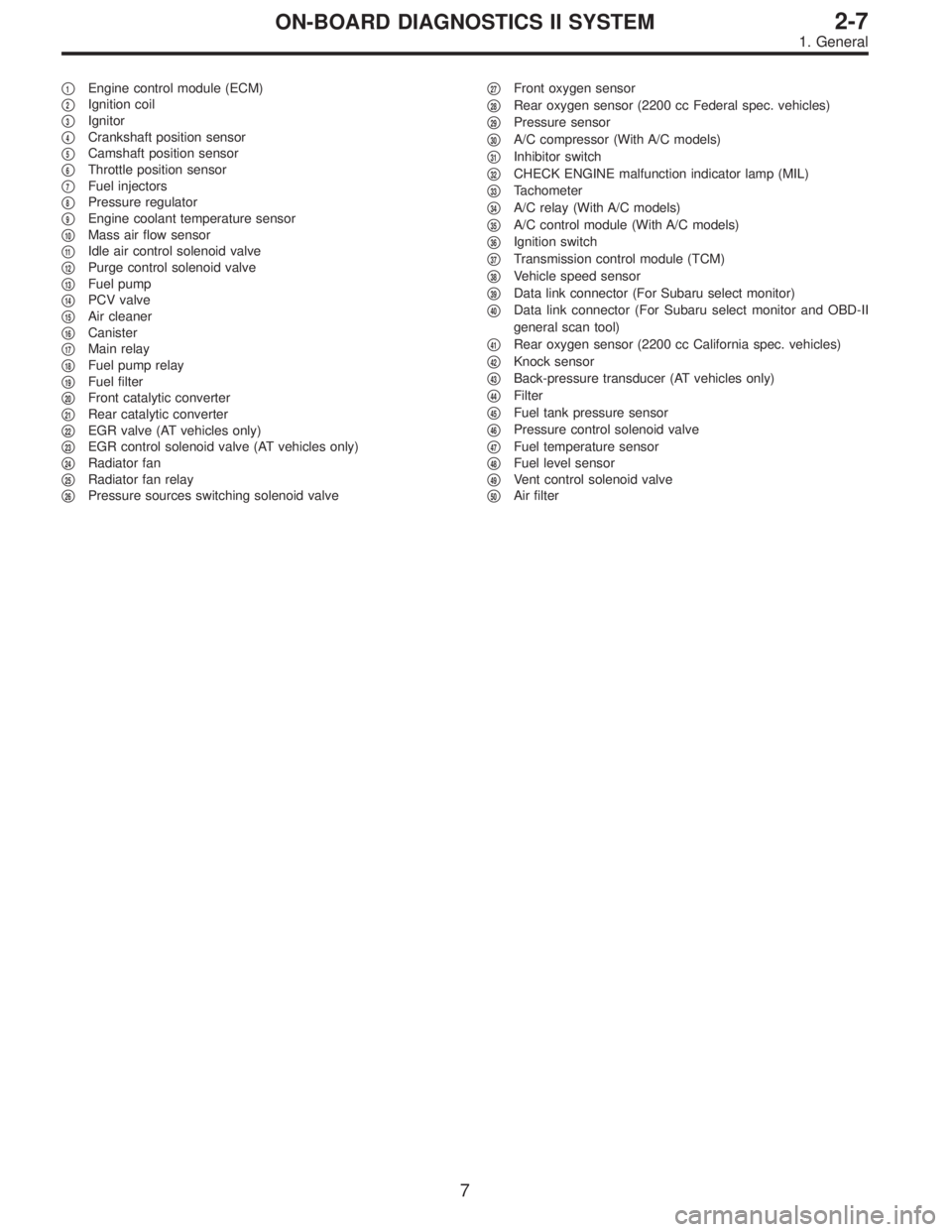
�1Engine control module (ECM)
�
2Ignition coil
�
3Ignitor
�
4Crankshaft position sensor
�
5Camshaft position sensor
�
6Throttle position sensor
�
7Fuel injectors
�
8Pressure regulator
�
9Engine coolant temperature sensor
�
10Mass air flow sensor
�
11Idle air control solenoid valve
�
12Purge control solenoid valve
�
13Fuel pump
�
14PCV valve
�
15Air cleaner
�
16Canister
�
17Main relay
�
18Fuel pump relay
�
19Fuel filter
�
20Front catalytic converter
�
21Rear catalytic converter
�
22EGR valve (AT vehicles only)
�
23EGR control solenoid valve (AT vehicles only)
�
24Radiator fan
�
25Radiator fan relay
�
26Pressure sources switching solenoid valve�
27Front oxygen sensor
�
28Rear oxygen sensor (2200 cc Federal spec. vehicles)
�
29Pressure sensor
�
30A/C compressor (With A/C models)
�
31Inhibitor switch
�
32CHECK ENGINE malfunction indicator lamp (MIL)
�
33Tachometer
�
34A/C relay (With A/C models)
�
35A/C control module (With A/C models)
�
36Ignition switch
�
37Transmission control module (TCM)
�
38Vehicle speed sensor
�
39Data link connector (For Subaru select monitor)
�
40Data link connector (For Subaru select monitor and OBD-II
general scan tool)
�
41Rear oxygen sensor (2200 cc California spec. vehicles)
�
42Knock sensor
�
43Back-pressure transducer (AT vehicles only)
�
44Filter
�
45Fuel tank pressure sensor
�
46Pressure control solenoid valve
�
47Fuel temperature sensor
�
48Fuel level sensor
�
49Vent control solenoid valve
�
50Air filter
7
2-7ON-BOARD DIAGNOSTICS II SYSTEM
1. General
Page 1860 of 3342

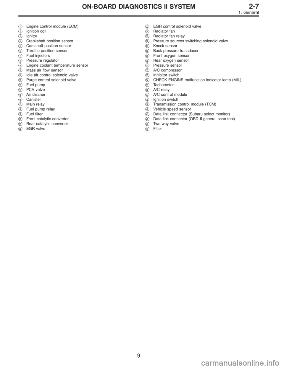
�1Engine control module (ECM)
�
2Ignition coil
�
3Ignitor
�
4Crankshaft position sensor
�
5Camshaft position sensor
�
6Throttle position sensor
�
7Fuel injectors
�
8Pressure regulator
�
9Engine coolant temperature sensor
�
10Mass air flow sensor
�
11Idle air control solenoid valve
�
12Purge control solenoid valve
�
13Fuel pump
�
14PCV valve
�
15Air cleaner
�
16Canister
�
17Main relay
�
18Fuel pump relay
�
19Fuel filter
�
20Front catalytic converter
�
21Rear catalytic converter
�
22EGR valve�
23EGR control solenoid valve
�
24Radiator fan
�
25Radiator fan relay
�
26Pressure sources switching solenoid valve
�
27Knock sensor
�
28Back-pressure transducer
�
29Front oxygen sensor
�
30Rear oxygen sensor
�
31Pressure sensor
�
32A/C compressor
�
33Inhibitor switch
�
34CHECK ENGINE malfunction indicator lamp (MIL)
�
35Tachometer
�
36A/C relay
�
37A/C control module
�
38Ignition switch
�
39Transmission control module (TCM)
�
40Vehicle speed sensor
�
41Data link connector (Subaru select monitor)
�
42Data link connector (OBD-II general scan tool)
�
43Two way valve
�
44Filter
9
2-7ON-BOARD DIAGNOSTICS II SYSTEM
1. General
Page 1975 of 3342
Symptom Problem parts
7. Spark knock1) Mass air flow sensor
2) Engine coolant temperature sensor
3) Knock sensor
4) Fuel injection parts (*4)
5) Fuel pump and fuel pump relay
8. After burning in exhaust system1) Mass air flow sensor
2) Engine coolant temperature sensor (*2)
3) Fuel injection parts (*4)
4) Fuel pump and fuel pump relay
*1: Check ignitor, ignition coil and spark plug.
*2: Indicate the symptom occurring only in cold temperatures.
*3: Ensure the secure installation.
*4: Check fuel injector, fuel pressure regulator and fuel filter.
*5: Inspect air leak in air intake system.
*6: Adjust accelerator cable.
124
2-7ON-BOARD DIAGNOSTICS II SYSTEM
9. General Diagnostic Table