Page 252 of 3342
G2M0088
6. Engine Oil Pressure
A: MEASUREMENT
1) Remove generator from bracket.
(1) Disconnect connector and terminal from generator.
G2M0089
(2) Remove V-belt cover.
(3) Loosen lock bolt and slider bolt, and remove V-belt
for generator.
G2M0090
(4) Remove generator lock bolt.
(5) Remove bolt which install generator on bracket.
G2M0091
2) Disconnect connector from oil pressure switch.
3) Remove oil pressure switch from engine cylinder block.
7
2-2
6. Engine Oil Pressure
Page 253 of 3342
G2M0093
4) Connect oil pressure gauge hose to cylinder block.
5) Start the engine, and measure oil pressure.
Oil pressure:
98 kPa (1.0 kg/cm
2,14 psi) or more at 800 rpm
294 kPa (3.0 kg/cm2, 43 psi) or more at 5,000 rpm
CAUTION:
�If oil pressure is out of specification, check oil
pump, oil filter and lubrication line.
�If oil pressure warning light is turned ON and oil
pressure is in specification, replace oil pressure
switch.
NOTE:
The specified data is based on an engine oil temperature
of 80°C (176°F).
6) After measuring oil pressure, install oil pressure switch.
Tightening torque:
25±3 N⋅m (2.5±0.3 kg-m, 18.1±2.2 ft-lb)
7) Install generator and V-belt in the reverse order of
removal, and adjust the V-belt deflection.
8
2-2
6. Engine Oil Pressure
Page 254 of 3342
 Set the vehicle onto the lift.
2) Disconnect batter")
7. Valve Clearance
A: INSPECTION
1. 2200 cc MODEL
CAUTION:
Inspection and adjustment of valve clearance should
be performed while engine is cold.
1) Set the vehicle onto the lift.
2) Disconnect battery ground cable.
3) Remove timing belt cover (RH).
B2M1225A
4) Remove rocker cover.
�When inspecting #1 and #3 cylinders;
(1) Disconnect connector from mass air flow sensor.
B2M1226A
(2) Loosen clamp which connects air intake duct to air
intake chamber.
(3) Remove the two clips from air cleaner upper cover.
CAUTION:
Before installing air cleaner upper cover, align hole(s)
with protruding portions of air cleaner lower case, then
secure upper cover.
(4) Disconnect blow-by hose from air intake duct.
B2M1227
(5) Remove air intake duct and air cleaner upper cover
as a unit.
(6) Remove air cleaner element.
(7) Disconnect spark plug cords from spark plugs (#1
and #3 cylinders).
(8) Remove under cover (RH).
(9) Place suitable container under the vehicle.
(10) Disconnect PCV hose from rocker cover (RH).
(11) Remove bolts, then remove rocker cover (RH).
9
2-2
7. Valve Clearance
Page 256 of 3342
 Similar to measurement procedures used for #1
cylinder, measure #2, #3 and #4 cylinder valve clearances.
NOTE:
�Be sure to set cylinder pistons to their respective top
dead centers on comp")
B2M1230A
8) Similar to measurement procedures used for #1
cylinder, measure #2, #3 and #4 cylinder valve clearances.
NOTE:
�Be sure to set cylinder pistons to their respective top
dead centers on compression stroke before measuring
valve clearances.
�To set #3, #2 and #4 cylinder pistons to their top dead
centers on compression stroke, turn crankshaft pulley
clockwise 90°at a time starting with arrow mark on right-
hand camshaft sprocket facing up.
9) After inspection, install the related parts in the reverse
order of removal.
2. 2500 cc MODEL
CAUTION:
Inspection and adjustment of valve clearance should
be performed while engine is cold.
1) Set the vehicle onto the lift.
2) Disconnect battery ground cable.
3) Remove canister.
4) Remove one bolt which secures timing belt cover (RH).
5) Lift-up the vehicle.
6) Remove under cover (RH).
7) Remove canister bracket.
8) Loosen remaining bolts which secure timing belt cover
(RH), then remove belt cover.
9) Lower the vehicle.
B2M1225A
10) Remove rocker cover.
�When inspecting #1 and #3 cylinders;
(1) Disconnect connector from mass air flow sensor.
11
2-2
7. Valve Clearance
Page 260 of 3342
B2M1230A
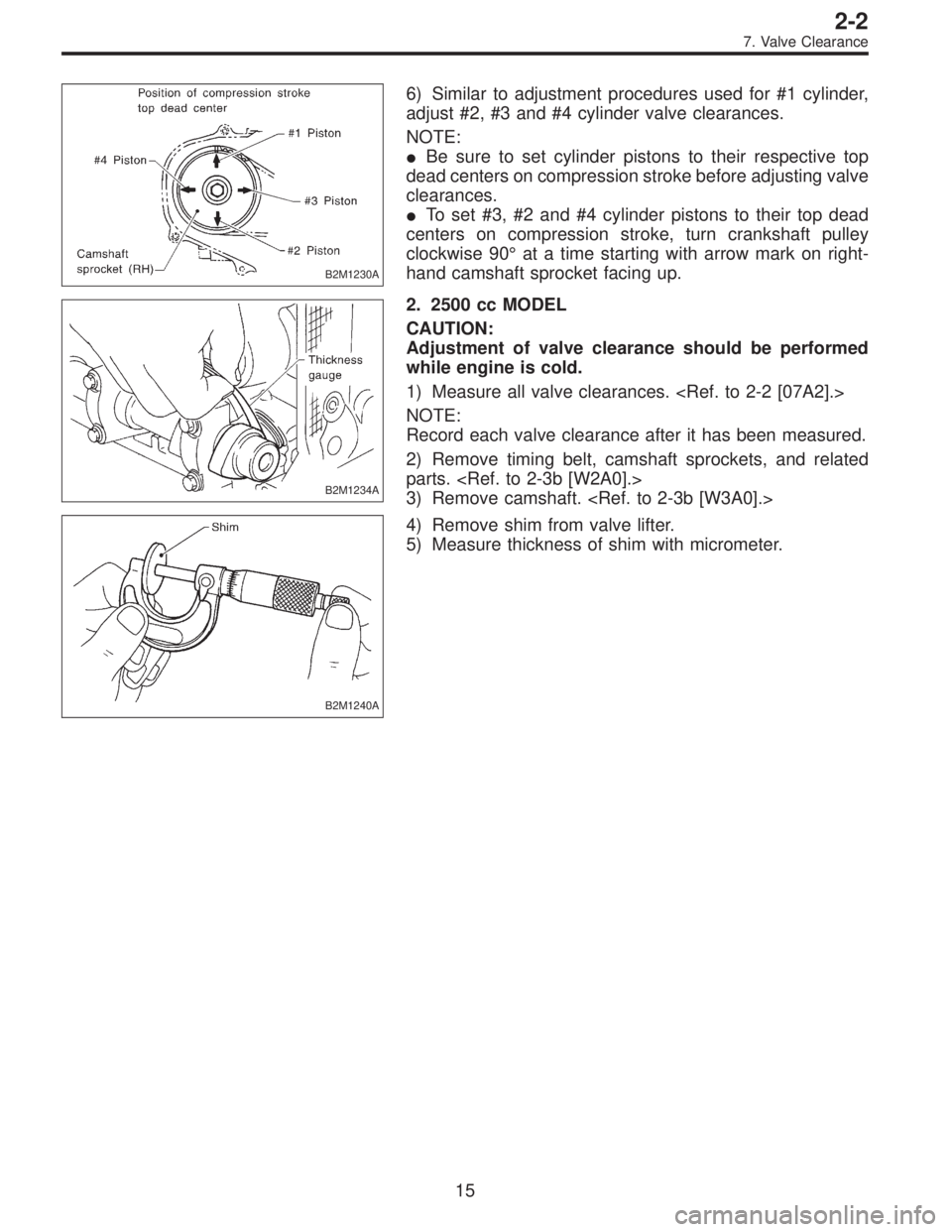
6) Similar to adjustment procedures used for #1 cylinder,
adjust #2, #3 and #4 cylinder valve clearances.
NOTE:
�Be sure to set cylinder pistons to their respective top
dead centers on compression stroke before adjusting valve
clearances.
�To set #3, #2 and #4 cylinder pistons to their top dead
centers on compression stroke, turn crankshaft pulley
clockwise 90°at a time starting with arrow mark on right-
hand camshaft sprocket facing up.
B2M1234A
2. 2500 cc MODEL
CAUTION:
Adjustment of valve clearance should be performed
while engine is cold.
1) Measure all valve clearances.
NOTE:
Record each valve clearance after it has been measured.
2) Remove timing belt, camshaft sprockets, and related
parts.
3) Remove camshaft.
B2M1240A
4) Remove shim from valve lifter.
5) Measure thickness of shim with micrometer.
15
2-2
7. Valve Clearance
Page 261 of 3342
 Select a shim of suitable thickness using measured
valve clearance and shim thickness, using the following
table.
Unit: mm
Intake valve:S=(V+T)�0.20
Exhaust valve:S=(V+T)�0.25
S: Shim thickness to")
6) Select a shim of suitable thickness using measured
valve clearance and shim thickness, using the following
table.
Unit: mm
Intake valve:S=(V+T)�0.20
Exhaust valve:S=(V+T)�0.25
S: Shim thickness to be used
V: Measured valve clearance
T: Shim thickness required
Part No. Thickness mm (in)
13218AC290 2.33 (0.0917)
13218AC300 2.34 (0.0921)
13218AC310 2.35 (0.0925)
13218AC320 2.36 (0.0929)
13218AC330 2.37 (0.0933)
13218AC340 2.38 (0.0937)
13218AC350 2.39 (0.0941)
13218AC360 2.40 (0.0945)
13218AC370 2.41 (0.0949)
13218AC380 2.42 (0.0953)
13218AC390 2.43 (0.0957)
13218AC400 2.44 (0.0961)
13218AC410 2.45 (0.0965)
13218AC420 2.46 (0.0969)
13218AC430 2.47 (0.0972)
13218AC440 2.48 (0.0976)
13218AC450 2.49 (0.0980)
13218AC460 2.50 (0.0984)
13218AC470 2.51 (0.0988)Part No. Thickness mm (in)
13218AC480 2.52 (0.0992)
13218AC490 2.53 (0.0996)
13218AC500 2.54 (0.1000)
13218AC510 2.55 (0.1004)
13218AC520 2.56 (0.1008)
13218AC530 2.57 (0.1012)
13218AC540 2.58 (0.1016)
13218AC550 2.59 (0.1020)
13218AC560 2.60 (0.1024)
13218AC570 2.61 (0.1028)
13218AC580 2.62 (0.1031)
13218AC590 2.63 (0.1035)
13218AC600 2.64 (0.1039)
13218AC610 2.65 (0.1043)
13218AC620 2.66 (0.1047)
13218AC630 2.67 (0.1051)
13218AC640 2.68 (0.1055)
13218AC650 2.69 (0.1059)
7) Set suitable shim selected in step 6) to valve lifter.
8) Install camshaft.
9) Install camshaft sprockets, timing belt and related parts.
NOTE:
At this point, do not install rocker cover.
16
2-2
7. Valve Clearance
Page 263 of 3342
1. Engine
A: SPECIFICATIONS
EngineModel2200 cc
TypeHorizontally opposed, liquid cooled, 4-cylinder, 4-stroke
gasoline engine
Valve arrangement Belt driven, single over-head camshaft, 4-valve/cylinder
Bore x Stroke mm (in) 96.9 x 75.0 (3.815 x 2.953)
Displacement cm
3(cu in) 2,212 (135.0)
Compression ratio9.7
Compression pressure
(at 200 — 300 rpm) kPa (kg/cm
2, psi)1,079 — 1,275
(11.0 — 13.0, 156 — 185)
Number of piston rings Pressure ring: 2, Oil ring: 1
Intake valve timingOpening 4° BTDC
Closing 52° ABDC
Exhaust valve timingOpening 48° BBDC
Closing 12° ATDC
Valve clearanceIntake mm (in) 0.20±0.02 (0.0079±0.0008)
Exhaust mm (in) 0.25±0.02 (0.0098±0.0008)
Idling speed
[At neutral position on MT, or
“P” or “N” position on AT] rpm700±100 (No load)
850±50 (A/C switch ON)
Firing order1,3,2,4
Ignition timing BTDC/rpm 14°±8°/700 (MT), 20°±8°/700 (AT)
2
2-3SPECIFICATIONS AND SERVICE DATA
1. Engine
Page 264 of 3342

Belt ten-
sionerSpacer O.D. 16 mm (0.63 in)
Tensioner bush I.D. 16.16 mm (0.6362 in)
Clearance between")
B: SERVICE DATA
Belt
tension
adjusterProtrusion of adjuster rod 15.4—16.4 mm (0.606—0.646 in)
Belt ten-
sionerSpacer O.D. 16 mm (0.63 in)
Tensioner bush I.D. 16.16 mm (0.6362 in)
Clearance between spacer and bushSTD 0.117—0.180 mm (0.0046—0.0071 in)
Limit 0.230 mm (0.0091 in)
Side clearance of spacerSTD 0.37—0.54 mm (0.0146—0.0213 in)
Limit 0.8 mm (0.031 in)
Valve
rocker armClearance between shaft and armSTD 0.020—0.054 mm (0.0008—0.0021 in)
Limit 0.10 mm (0.0039 in)
CamshaftBend limit 0.025 mm (0.0010 in)
Thrust clearanceSTD 0.030—0.260 mm (0.0012—0.0102 in)
Limit 0.35 mm (0.0138 in)
Cam lobe heightIntakeSTD 32.244—32.344 mm (1.2694—1.2734 in)
Limit 32.094 mm (1.2635 in)
ExhaustSTD 31.964—32.064 mm (1.2584—1.2624 in)
Limit 31.814 mm (1.2525 in)
Camshaft journal O.D. RHFront
LHRear 31.935—31.950 mm (1.2573—1.2579 in)
Center Center 37.435—37.450 mm (1.4738—1.4744 in)
Rear Front 37.935—37.950 mm (1.4935—1.4941 in)
Camshaft journal hole
I.D.RHFront
LHRear 32.005—32.025 mm (1.2600—1.2608 in)
Center Center 37.505—37.525 mm (1.4766—1.4774 in)
Rear Front 38.005—38.025 mm (1.4963—1.4970 in)
Oil clearanceSTD 0.055—0.090 mm (0.0022—0.0035 in)
Limit 0.10 mm (0.0039 in)
Cylinder
headSurface warpage limit 0.05 mm (0.0020 in)
Surface grinding limit 0.1 mm (0.004 in)
Standard height 98.3 mm (3.870 in)
Valve setRefacing angle 90°
Contacting widthIntakeSTD 0.7 mm (0.028 in)
Limit 1.4 mm (0.055 in)
ExhaustSTD 1.4 mm (0.055 in)
Limit 1.8 mm (0.071 in)
Valve
guideInner diameter 6.000—6.012 mm (0.2362—0.2367 in)
Protrusion above head 17.5—18.0 mm (0.689—0.709 in)
ValveHead edge thicknessIntakeSTD 1.0 mm (0.039 in)
Limit 0.8 mm (0.031 in)
ExhaustSTD 1.2 mm (0.047 in)
Limit 0.8 mm (0.031 in)
Stem diameterIntake 5.950—5.965 mm (0.2343—0.2348 in)
Exhaust 5.945—5.960 mm (0.2341—0.2346 in)
Stem oil clearanceSTDIntake 0.035—0.062 mm (0.0014—0.0024 in)
Exhaust 0.040—0.067 mm (0.0016—0.0026 in)
Limit—0.15 mm (0.0059 in)
Overall lengthIntake 101.0 mm (3.976 in)
Exhaust 101.2 mm (3.984 in)
STD: Standard I.D.: Inner Diameter O.D.: Outer Diameter
3
2-3SPECIFICATIONS AND SERVICE DATA
1. Engine
 Remove generator from bracket.
(1) Disconnect connector and terminal from generator.
G2M0089
(2) Remove V-belt cover.
(3) Loosen lock bolt and slider b")
 Connect oil pressure gauge hose to cylinder block.
5) Start the engine, and measure oil pressure.
Oil pressure:
98 kPa (1.0 kg/cm
2,14 psi) or more at 800 rpm
294 kPa (3.0 kg/cm2, 43 psi) o")