Page 343 of 3342

1. Engine
A: SPECIFICATIONS
EngineModel2500 cc
TypeHorizontally opposed, liquid cooled, 4-cylinder, 4-stroke
gasoline engine
Valve arrangement Belt driven, double over-head camshaft, 4-valve/cylinder
Bore x Stroke mm (in) 99.5 x 79.0 (3.917 x 3.110)
Displacement cm
3(cu in) 2,457 (149.93)
Compression ratio9.5
Compression pressure
(at 200 — 300 rpm)
kPa (kg/cm
2, psi) � rpmStandard 1,216 (12.4, 176) � 350
Limit 941 (9.6, 137) � 350
Number of piston rings Pressure ring: 2, Oil ring: 1
Intake valve timingOpening 6° BTDC
Closing 50° ABDC
Exhaust valve timingOpening Front: 54° BBDC, Rear: 30° BBDC (Position in degrees)
Closing Front: 10° ATDC, Rear: 10° ATDC (Position in degrees)
Valve clearanceIntake mm (in) 0.20±0.02 (0.0079±0.0008)
Exhaust mm (in) 0.25±0.02 (0.0098±0.0008)
Idling speed
[At neutral position on MT, or
“P” or “N” position on AT] rpm700±100 (No load)
850±50 (A/C switch ON)
Firing order1,3,2,4
Ignition timing BTDC/rpm 15°±8°/700 rpm
2
2-3bSPECIFICATIONS AND SERVICE DATA
1. Engine
Page 344 of 3342

Belt ten-
sionerSpacer O.D. 16 mm (0.63 in)
Tensioner bush I.D. 16.16 mm (0.6362 in)
Clearance between")
B: SERVICE DATA
Belt
tension
adjusterProtrusion of adjuster rod 15.4—16.4 mm (0.606—0.646 in)
Belt ten-
sionerSpacer O.D. 16 mm (0.63 in)
Tensioner bush I.D. 16.16 mm (0.6362 in)
Clearance between spacer and bushSTD 0.117—0.180 mm (0.0046—0.0071 in)
Limit 0.230 mm (0.0091 in)
Side clearance of spacerSTD 0.37—0.54 mm (0.0146—0.0213 in)
Limit 0.8 mm (0.031 in)
CamshaftBend limit 0.020 mm (0.0008 in)
Thrust clearanceSTD 0.040—0.080 mm (0.0016—0.0031 in)
Limit 0.10 mm (0.0039 in)
Cam lobe heightIntakeSTD 42.20—42.30 mm (1.6614—1.6654 in)
Limit 42.04 mm (1.6551 in)
ExhaustSTDFront: 42.50—42.60 mm
Rear: 41.40—41.50 mm(1.6732—1.6772 in)
(1.6299—1.6339 in)
LimitFront: 42.34 mm
Rear: 41.24 mm(1.6669 in)
(1.6236 in)
Camshaft journal O.D.Front 31.946—31.963 mm (1.2577—1.2584 in)
Center 27.946—27.963 mm (1.1002—1.1009 in)
Rear 27.946—27.963 mm (1.1002—1.1009 in)
Camshaft journal hole I.D.Front 32.000—32.018 mm (1.2598—1.2605 in)
Center 28.000—28.018 mm (1.1024—1.1031 in)
Rear 28.000—28.018 mm (1.1024—1.1031 in)
Oil clearanceSTD 0.037—0.072 mm (0.0015—0.0028 in)
Limit 0.10 mm (0.0039 in)
Cylinder
headSurface warpage limit 0.05 mm (0.0020 in)
Surface grinding limit 0.3 mm (0.012 in)
Standard height 127.5 mm (5.02 in)
Valve seatRefacing angle 90°
Contacting widthIntakeSTD 1.0 mm (0.039 in)
Limit 1.7 mm (0.067 in)
ExhaustSTD 1.5 mm (0.059 in)
Limit 2.2 mm (0.087 in)
Valve
guideInner diameter 6.000—6.015 mm (0.2362—0.2368 in)
Protrusion above head 12.0—12.4 mm (0.472—0.488 in)
ValveHead edge thicknessIntakeSTD 1.2 mm (0.047 in)
Limit 0.8 mm (0.031 in)
ExhaustSTD 1.5 mm (0.059 in)
Limit 0.8 mm (0.031 in)
Stem diameterIntake 5.950—5.965 mm (0.2343—0.2348 in)
Exhaust 5.950—5.965 mm (0.2343—0.2348 in)
Stem oil clearanceSTDIntake 0.035—0.062 mm (0.0014—0.0024 in)
Exhaust 0.040—0.067 mm (0.0016—0.0026 in)
Limit—0.15 mm (0.0059 in)
Overall lengthIntake 105.9 mm (4.169 in)
Exhaust 106.2 mm (4.181 in)
STD: Standard I.D.: Inner Diameter O.D.: Outer Diameter
3
2-3bSPECIFICATIONS AND SERVICE DATA
1. Engine
Page 347 of 3342
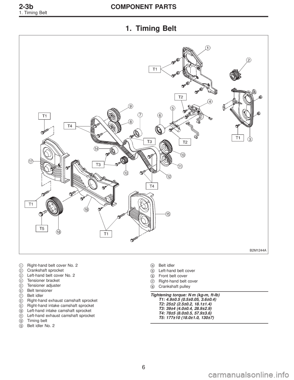
1. Timing Belt
B2M1244A
�1Right-hand belt cover No. 2
�
2Crankshaft sprocket
�
3Left-hand belt cover No. 2
�
4Tensioner bracket
�
5Tensioner adjuster
�
6Belt tensioner
�
7Belt idler
�
8Right-hand exhaust camshaft sprocket
�
9Right-hand intake camshaft sprocket
�
10Left-hand intake camshaft sprocket
�
11Left-hand exhaust camshaft sprocket
�
12Timing belt
�
13Belt idler No. 2�
14Belt idler
�
15Left-hand belt cover
�
16Front belt cover
�
17Right-hand belt cover
�
18Crankshaft pulley
Tightening torque: N⋅m (kg-m, ft-lb)
T1: 4.9±0.5 (0.5±0.05, 3.6±0.4)
T2: 25±2 (2.5±0.2, 18.1±1.4)
T3: 39±4 (4.0±0.4, 28.9±2.9)
T4: 78±5 (8.0±0.5, 57.9±3.6)
T5: 177±10 (18.0±1.0, 130±7)
6
2-3bCOMPONENT PARTS
1. Timing Belt
Page 352 of 3342
G2M0709
1. General Precautions
1) Before disassembling engine, place it on ST3.
ST1 498457000 ENGINE STAND ADAPTER RH
ST2 498457100 ENGINE STAND ADAPTER LH
ST3 499817000 ENGINE STAND
2) All parts should be thoroughly cleaned, paying special
attention to the engine oil passages, pistons and bearings.
3) Rotating parts and sliding parts such as piston, bearing
and gear should be coated with oil prior to assembly.
4) Be careful not to let oil, grease or coolant contact the
timing belt, clutch disc and flywheel.
5) All removed parts, if to be reused, should be reinstalled
in the original positions and directions.
6) Gaskets and lock washers must be replaced with new
ones. Liquid gasket should be used where specified to
prevent leakage.
7) Bolts, nuts and washers should be replaced with new
ones as required.
8) Even if necessary inspections have been made in
advance, proceed with assembly work while making
rechecks.
11
2-3bSERVICE PROCEDURE
1. General Precautions
Page 353 of 3342
2. Timing Belt
A: REMOVAL
1. CRANKSHAFT PULLEY AND BELT COVER
B2M1215A
G2M0711
1) Remove V-belt cover, V-belt and air conditioning com-
pressor drive belt tensioner.
2) Remove pulley bolt. To lock crankshaft, use ST.
ST 499977100 CRANKSHAFT PULLEY WRENCH
3) Remove crankshaft pulley.
B2M0729
4) Remove left-hand belt cover.
12
2-3bSERVICE PROCEDURE
2. Timing Belt
Page 354 of 3342
B2M0730
5) Remove right-hand belt cover.
B2M0731
6) Remove front belt cover.
13
2-3bSERVICE PROCEDURE
2. Timing Belt
Page 355 of 3342
2. TIMING BELT
B2M0685A
G2M0713
B2M0686A
1) If alignment mark and/or arrow mark (which indicates
rotation direction) on timing belt fade away, put new marks
before removing timing belt as follows:
(1) Turn crankshaft using ST, and align alignment
marks on crankshaft sprocket, left-hand intake cam-
shaft sprocket, left-hand exhaust camshaft sprocket,
right-hand intake camshaft sprocket and right hand
exhaust camshaft sprocket with notches of belt cover
and cylinder block.
ST 499987500 CRANKSHAFT SOCKET
14
2-3bSERVICE PROCEDURE
2. Timing Belt
Page 356 of 3342
B2M0687A
(2) Using white paint, put alignment and/or arrow
marks on timing belts in relation to the sprockets.
Z
1: 54.5 tooth length
Z
2: 51 tooth length
Z
3: 28 tooth length
B2M0688
B2M0689
G2M0739
2) Loosen tensioner adjuster mounting bolts.
3) Remove belt idler.
B2M0733
4) Remove timing belt.
5) Remove belt idler No. 2.
CAUTION:
After timing belt has been removed, never rotate intake
and exhaust, camshaft sprocket.
If camshaft sprocket is rotated, the intake and exhaust
valve heads strike together and valve stems are bent.
15
2-3bSERVICE PROCEDURE
2. Timing Belt
 Before disassembling engine, place it on ST3.
ST1 498457000 ENGINE STAND ADAPTER RH
ST2 498457100 ENGINE STAND ADAPTER LH
ST3 499817000 ENGINE STAND
2) All parts shou")
![SUBARU LEGACY 1997 Service Repair Manual 2. Timing Belt
A: REMOVAL
1. CRANKSHAFT PULLEY AND BELT COVER
B2M1215A
G2M0711
1) Remove V-belt cover, V-belt and air conditioning com-
pressor drive belt tensioner. <Ref. to 1-5 [01A0].>
2) Remove pu](/manual-img/17/57434/w960_57434-352.png "SUBARU LEGACY 1997 Service Repair Manual 2. Timing Belt
A: REMOVAL
1. CRANKSHAFT PULLEY AND BELT COVER
B2M1215A
G2M0711
1) Remove V-belt cover, V-belt and air conditioning com-
pressor drive belt tensioner. <Ref. to 1-5 [01A0].>
2) Remove pu")
 Remove right-hand belt cover.
B2M0731
6) Remove front belt cover.
13
2-3bSERVICE PROCEDURE
2. Timing Belt")
 If alignment mark and/or arrow mark (which indicates
rotation direction) on timing belt fade away, put new marks
before removing timing belt as follows:
(1)")
 Using white paint, put alignment and/or arrow
marks on timing belts in relation to the sprockets.
Z
1: 54.5 tooth length
Z
2: 51 tooth length
Z
3: 28 tooth length
B2M0688
B2M0689
G2M0739")