Page 365 of 3342
G2M0728
1) Crankshaft and camshaft sprocket alignment
(1) Align mark on crankshaft sprocket with mark on the
oil pump cover at cylinder block.
B2M0694A
(2) Align single line mark on right-hand exhaust cam-
shaft sprocket with notch on belt cover.
B2M0695A
(3) Align single line mark on right-hand exhaust cam-
shaft sprocket with notch on belt cover.
(Make sure double lines on intake camshaft and
exhaust camshaft sprockets are aligned.)
B2M0696A
(4) Align single line mark on left-hand exhaust cam-
shaft sprocket with notch on belt cover by turning
sprocket counter-clockwise (as viewed from front of
engine).
B2M0697A
(5) Align single line mark on left-hand intake camshaft
sprocket with notch on belt cover by turning sprocket
clockwise (as viewed from front of engine).
Ensure double lines on intake and exhaust camshaft
sprockets are aligned.
24
2-3bSERVICE PROCEDURE
2. Timing Belt
Page 366 of 3342
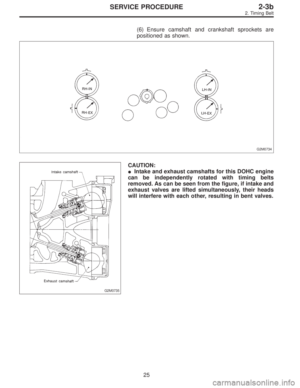
(6) Ensure camshaft and crankshaft sprockets are
positioned as shown.
G2M0734
G2M0735
CAUTION:
�Intake and exhaust camshafts for this DOHC engine
can be independently rotated with timing belts
removed. As can be seen from the figure, if intake and
exhaust valves are lifted simultaneously, their heads
will interfere with each other, resulting in bent valves.
25
2-3bSERVICE PROCEDURE
2. Timing Belt
Page 367 of 3342

B2M0698A
�When timing belts are not installed, four camshafts
are held at the“zero-lift”position, where all cams on
camshafts do not push intake and exhaust valves
down. (Under this condition, all valves remain
unlifted.)
�When camshafts are rotated to install timing belts,
#2 intake and #4 exhaust cam of left-hand camshafts
are held to push their corresponding valves down.
(Under this condition, these valves are held lifted.)
Right-side camshafts are held so that their cams do
not push valves down.
�Left-hand camshafts must be rotated from the“zero-
lift”position to the position where timing belt is to be
installed at as small an angle as possible, in order to
prevent mutual interference of intake and exhaust
valve heads.
�Do not allow camshafts to rotate in the direction
shown in the upper of figure as this causes both intake
and exhaust valves to lift simultaneously, resulting in
interference with their heads.
B2M0699
2) Installation of timing belt
Align alignment mark on timing belt with marks on sprock-
ets in the numerical order shown in figure. While aligning
marks, position timing belt properly.
CAUTION:
Ensure belt’s rotating direction is correct.
G2M0738
26
2-3bSERVICE PROCEDURE
2. Timing Belt
Page 368 of 3342
G2M0739
3) Install belt idler.
CAUTION:
Make sure that the marks on timing belt and sprockets
are aligned.
B2M0700
4) Loosen tension adjuster attaching bolts and move
adjuster all the way to the left. Tighten the bolts.
G2M0741
5) After ensuring that the marks on timing belt and sprock-
ets are aligned, remove stopper pin from tension adjuster.
27
2-3bSERVICE PROCEDURE
2. Timing Belt
Page 369 of 3342
4. CRANKSHAFT PULLEY AND BELT COVER
B2M1215B
Tightening torque: N⋅m (kg-m, ft-lb)
T1: 5±0.5 (0.5±0.05, 3.6±0.4)
T2: 177±10 (18.0±1.0, 130±7)
B2M0731
1) Install front belt cover.
B2M0730
2) Install right-hand belt cover.
B2M0729
3) Install left-hand belt cover.
4) Install crankshaft pulley.
28
2-3bSERVICE PROCEDURE
2. Timing Belt
Page 370 of 3342
G2M0711
5) Install pulley bolt by using ST.
ST 499977100 CRANKSHAFT PULLEY WRENCH
6) Install V-belt.
CAUTION:
After installing V-belt, check and adjust V-belt tension.
29
2-3bSERVICE PROCEDURE
2. Timing Belt
Page 371 of 3342
3. Camshaft
A: REMOVAL
1. RELATED PARTS
Remove timing belt, camshaft sprockets and related parts.
2. CAMSHAFT LH
G2M0743
1) Remove camshaft position sensor.
2) Remove ignition coils.
3) Remove rocker cover and gasket.
G2M0744
4) Loosen intake camshaft cap bolts equally, a little at a
time in the numerical sequence shown in figure.
5) Remove camshaft caps and intake camshaft.
30
2-3bSERVICE PROCEDURE
3. Camshaft
Page 374 of 3342
C: INSTALLATION
1. CAMSHAFT
B2M1304F
Tightening torque: N⋅m (kg-m, ft-lb)
T1: 5±0.5 (0.5±0.05, 3.6±0.4)
T2: 10±0.7 (1.0±0.07, 7.2±0.5)
T3: 20±2 (2.0±0.2, 14.5±1.4)
B2M1200A
1) Camshaft installation
Apply engine oil to cylinder head at camshaft bearing loca-
tion before installing camshaft. Install camshaft so that
rocker arm is close to or in contact with“base circle”of cam
lobe.
CAUTION:
�When camshafts are positioned as shown in figure,
camshafts need to be rotated at a minimum to align
with timing belt during installation.
�Right-hand camshaft need not be rotated when set
at position shown in figure.
Left-hand intake camshaft: Rotate 80°clockwise.
Left-hand exhaust camshaft: Rotate 45°counter-clock-
wise.
33
2-3bSERVICE PROCEDURE
3. Camshaft
 Crankshaft and camshaft sprocket alignment
(1) Align mark on crankshaft sprocket with mark on the
oil pump cover at cylinder block.
B2M0694A
(2) Align single line mark on right-hand exhaust")
 Install belt idler.
CAUTION:
Make sure that the marks on timing belt and sprockets
are aligned.
B2M0700
4) Loosen tension adjuster attaching bolts and move
adjuster all the way to the left.")

T1: 5±0.5 (0.5±0.05, 3.6±0.4)
T2: 177±10 (18.0±1.0, 130±7)
B2M0731
1) Install front belt cover.
B2M0730
2) Ins")
 Install pulley bolt by using ST.
ST 499977100 CRANKSHAFT PULLEY WRENCH
6) Install V-belt.
CAUTION:
After installing V-belt, check and adjust V-belt tension.
29
2-3bSERVICE PROCEDURE
2. Timi")
![SUBARU LEGACY 1997 Service Repair Manual 3. Camshaft
A: REMOVAL
1. RELATED PARTS
Remove timing belt, camshaft sprockets and related parts.
<Ref. to 2-3b [W2A0].>
2. CAMSHAFT LH
G2M0743
1) Remove camshaft position sensor.
2) Remove ignition c](/manual-img/17/57434/w960_57434-370.png "SUBARU LEGACY 1997 Service Repair Manual 3. Camshaft
A: REMOVAL
1. RELATED PARTS
Remove timing belt, camshaft sprockets and related parts.
<Ref. to 2-3b [W2A0].>
2. CAMSHAFT LH
G2M0743
1) Remove camshaft position sensor.
2) Remove ignition c")

T1: 5±0.5 (0.5±0.05, 3.6±0.4)
T2: 10±0.7 (1.0±0.07, 7.2±0.5)
T3: 20±2 (2.0±0.2, 14.5±1.4)
B2M1200A
1) Camshaft inst")