Page 1176 of 3342
B4M0051
7. Full Wheel Cap
A: REMOVAL
Pry off the full wheel cap with a wheel cap remover inserted
between openings in the cap.
B: INSTALLATION
Align the valve hole in the wheel cap with the valve on the
wheel and secure the wheel cap by tapping four points by
hand.
8. Steel Wheel and Tire
1) Deformation or damage on the rim can cause air leak-
age. Check the rim flange for deformation, crack, or
damage, and repair or replace as necessary.
2) Take stone, glass, nail etc. off the tread groove.
G4M0297
3) Replace tire:
�when large crack on side wall, damage or crack on
tread is found.
�when the“tread wear indicator”appears as a solid
band across the tread.
CAUTION:
�When replacing a tire, make sure to use only the
same size, construction and load range as originally
installed.
�Avoid mixing radial, belted bias or bias tires on the
vehicle.
49
4-2SERVICE PROCEDURE
7. Full Wheel Cap - 8. Steel Wheel and Tire
Page 1177 of 3342
B4M0051
7. Full Wheel Cap
A: REMOVAL
Pry off the full wheel cap with a wheel cap remover inserted
between openings in the cap.
B: INSTALLATION
Align the valve hole in the wheel cap with the valve on the
wheel and secure the wheel cap by tapping four points by
hand.
8. Steel Wheel and Tire
1) Deformation or damage on the rim can cause air leak-
age. Check the rim flange for deformation, crack, or
damage, and repair or replace as necessary.
2) Take stone, glass, nail etc. off the tread groove.
G4M0297
3) Replace tire:
�when large crack on side wall, damage or crack on
tread is found.
�when the“tread wear indicator”appears as a solid
band across the tread.
CAUTION:
�When replacing a tire, make sure to use only the
same size, construction and load range as originally
installed.
�Avoid mixing radial, belted bias or bias tires on the
vehicle.
49
4-2SERVICE PROCEDURE
7. Full Wheel Cap - 8. Steel Wheel and Tire
Page 1189 of 3342
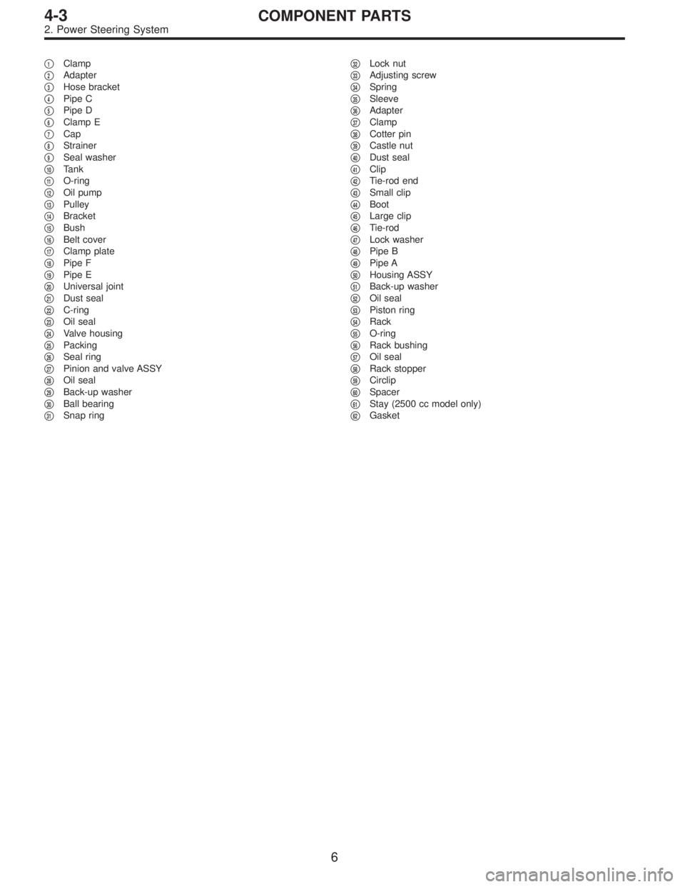
�1Clamp
�
2Adapter
�
3Hose bracket
�
4Pipe C
�
5Pipe D
�
6Clamp E
�
7Cap
�
8Strainer
�
9Seal washer
�
10Tank
�
11O-ring
�
12Oil pump
�
13Pulley
�
14Bracket
�
15Bush
�
16Belt cover
�
17Clamp plate
�
18Pipe F
�
19Pipe E
�
20Universal joint
�
21Dust seal
�
22C-ring
�
23Oil seal
�
24Valve housing
�
25Packing
�
26Seal ring
�
27Pinion and valve ASSY
�
28Oil seal
�
29Back-up washer
�
30Ball bearing
�
31Snap ring�
32Lock nut
�
33Adjusting screw
�
34Spring
�
35Sleeve
�
36Adapter
�
37Clamp
�
38Cotter pin
�
39Castle nut
�
40Dust seal
�
41Clip
�
42Tie-rod end
�
43Small clip
�
44Boot
�
45Large clip
�
46Tie-rod
�
47Lock washer
�
48Pipe B
�
49Pipe A
�
50Housing ASSY
�
51Back-up washer
�
52Oil seal
�
53Piston ring
�
54Rack
�
55O-ring
�
56Rack bushing
�
57Oil seal
�
58Rack stopper
�
59Circlip
�
60Spacer
�
61Stay (2500 cc model only)
�
62Gasket
6
4-3COMPONENT PARTS
2. Power Steering System
Page 1191 of 3342
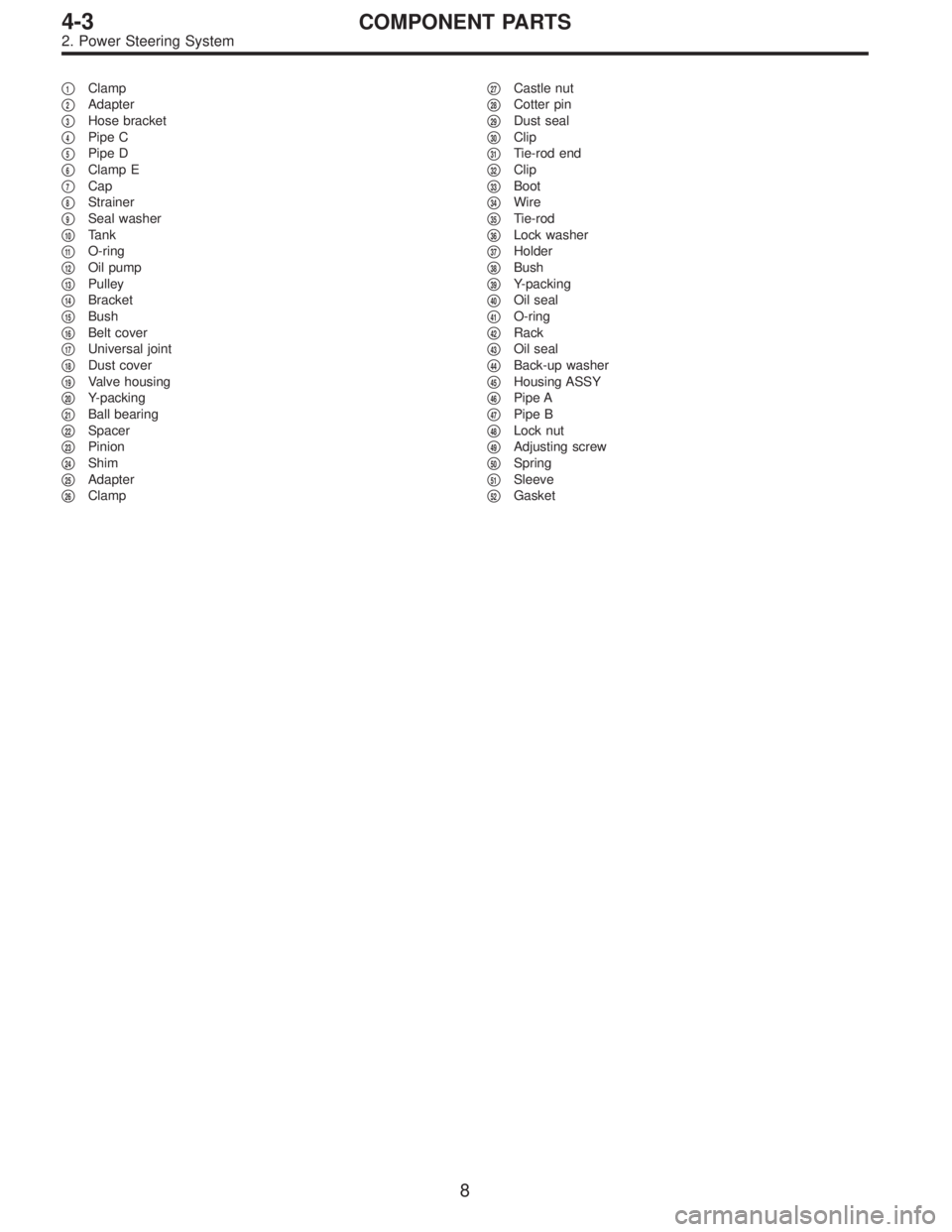
�1Clamp
�
2Adapter
�
3Hose bracket
�
4Pipe C
�
5Pipe D
�
6Clamp E
�
7Cap
�
8Strainer
�
9Seal washer
�
10Tank
�
11O-ring
�
12Oil pump
�
13Pulley
�
14Bracket
�
15Bush
�
16Belt cover
�
17Universal joint
�
18Dust cover
�
19Valve housing
�
20Y-packing
�
21Ball bearing
�
22Spacer
�
23Pinion
�
24Shim
�
25Adapter
�
26Clamp�
27Castle nut
�
28Cotter pin
�
29Dust seal
�
30Clip
�
31Tie-rod end
�
32Clip
�
33Boot
�
34Wire
�
35Tie-rod
�
36Lock washer
�
37Holder
�
38Bush
�
39Y-packing
�
40Oil seal
�
41O-ring
�
42Rack
�
43Oil seal
�
44Back-up washer
�
45Housing ASSY
�
46Pipe A
�
47Pipe B
�
48Lock nut
�
49Adjusting screw
�
50Spring
�
51Sleeve
�
52Gasket
8
4-3COMPONENT PARTS
2. Power Steering System
Page 1247 of 3342
 Disconnect pipe C⋅D from pipe (on the gearbox side).
CAUTION:
�When disconnecting pipe C⋅D, use two wrenches to
prevent deformities.
�Be careful to keep pipe connections free from for-")
G4M0101
5) Disconnect pipe C⋅D from pipe (on the gearbox side).
CAUTION:
�When disconnecting pipe C⋅D, use two wrenches to
prevent deformities.
�Be careful to keep pipe connections free from for-
eign matter.
B4M1159A
6) Remove bolt A.
Disconnect pipe C from oil pump. Disconnect pipe D from
oil tank.
CAUTION:
�Do not allow fluid from the hose end to come into
contact with pulley belt.
�To prevent foreign matter from entering the hose
and pipe, cover the open ends of them with a clean
cloth.
G4M0098
2. RHD MODEL
1) Disconnect battery negative terminal.
B4M0671A
2) Lift vehicle and remove jack-up plate.
3) Remove one pipe joint at the center of gearbox, and
connect vinyl hose to pipe and joint. Discharge fluid by
turning steering wheel fully clockwise and counterclock-
wise. Discharge fluid similarly from the other pipe.
CAUTION:
Improper removal and installation of parts often
causes fluid leak trouble. To prevent this, clean the
surrounding portions before disassembly and
reassembly, and pay special attention to keep dirt and
other foreign matter from mating surfaces.
63
4-3SERVICE PROCEDURE
7. Pipe Assembly (Power Steering System)
Page 1248 of 3342
 Remove clamp E from pipes C and D.
5) Remove flare nuts from control valve of gearbox
assembly, and then disconnect pipe C⋅D.
CAUTION:
�When disconnecting pipe C⋅D, use two wrenches to")
B4M0672A
4) Remove clamp E from pipes C and D.
5) Remove flare nuts from control valve of gearbox
assembly, and then disconnect pipe C⋅D.
CAUTION:
�When disconnecting pipe C⋅D, use two wrenches to
prevent deformities.
�Be careful to keep pipe connections free from for-
eign matter.
B4M1159A
6) Remove bolt A.
Disconnect pipe C from oil pump. Disconnect pipe D from
oil tank.
CAUTION:
�Do not allow fluid from the hose end to come into
contact with pulley belt.
�To prevent foreign matter from entering the hose
and pipe, cover the open ends of them with a clean
cloth.
B: CHECK
Check all disassembled parts for wear, damage or other
abnormalities. Repair or replace faulty parts as required.
Part name Inspection Remedy
Pipe�O-ring fitting surface for
damage
�Nut for damage
�Pipe for damageReplace with new one.
Clamp
�Clamps for weak
clamping forceReplace with new one.
Clamp E
Hose�Flared surface for
damage
�Flare nut for damage
�Outer surface for cracks
�Outer surface for wear
�Clip for damage
�End coupling or adapter
for degradationReplace with new one.
64
4-3SERVICE PROCEDURE
7. Pipe Assembly (Power Steering System)
Page 1254 of 3342

A: REMOVAL
1) Remove ground cable from battery.
2) Drain the working fluid about 0.35�(0.4 US qt, 0.3 Imp
qt) from oil tank.
3) Remove pulley belt cover bra")
B4M1160
8. Oil Pump (Power Steering System)
A: REMOVAL
1) Remove ground cable from battery.
2) Drain the working fluid about 0.35�(0.4 US qt, 0.3 Imp
qt) from oil tank.
3) Remove pulley belt cover bracket.
B4M1161A
4) Loosen oil pump pulley nut, then remove bolts which
secure alternator.
5) Loosen pulley belt(s).
6) Remove the nut and detach oil pump pulley.
B4M1159A
7) Remove bolt A. Disconnect pipe C from oil pump. Dis-
connect pipe D from oil tank.
CAUTION:
�Do not allow fluid from the hose end to come into
contact with pulley belt.
�To prevent foreign matter from entering the hose
and pipe, cover the open ends of them with a clean
cloth.
�Except when only oil tank needs to be inspected,
detach oil tank and oil pump as a unit. Then separate
one from the other on a work bench to prevent oil from
spilling on any part of the engine.
B4M0560
8) Remove three bolts from the front side of oil pump and
detach the pump.
9) Remove three bolts from the lower side of bracket and
detach the bracket.
CAUTION:
The bracket does not need to be removed unless it is
damaged.
70
4-3SERVICE PROCEDURE
8. Oil Pump (Power Steering System)
Page 1263 of 3342
 Install stay to oil pump. (2500 cc model only)
Tightening torque:
15.7±2.5 N⋅m (1.6±0.25 kg-m, 11.6±1.8 ft-lb)
B4M0560
7) Install oil pump, previously assembled to oil tank, on
bracke")
B4M1163A
6) Install stay to oil pump. (2500 cc model only)
Tightening torque:
15.7±2.5 N⋅m (1.6±0.25 kg-m, 11.6±1.8 ft-lb)
B4M0560
7) Install oil pump, previously assembled to oil tank, on
bracket.
Tightening torque:
20.1±2.5 N⋅m (2.05±0.25 kg-m, 14.8±1.8 ft-lb)
8) Place oil pump pulley and tighten pulley nut temporarily.
B4M1159A
9) Interconnect pipes C and D.
Tightening torque:
Joint nut
15±5 N⋅m (1.5±0.5 kg-m, 10.8±3.6 ft-lb)
CAUTION:
If a hose is twisted at this step, the hose may come into
contact with some other parts.
10) Connect pipe D from oil tank.
11) Connect pipe C from oil pump.
CAUTION:
Use a new gasket.
Tightening torque:
34±5 N⋅m (3.5±0.5 kg-m, 25.3±3.6 ft-lb)
12) Tighten bolt A.
Tightening torque:
13±3 N⋅m (1.3±0.3 kg-m, 9.4±2.2 ft-lb)
13) Install pulley belt to oil pump.
14) Tighten oil pump pulley nut to the specified torque.
Tightening torque:
61±7 N⋅m (6.2±0.7 kg-m, 44.8±5.1 ft-lb)
15) Adjust pulley belt tension.
16) Tighten bolt belt tension.
Tightening torque:
8±2 N⋅m (0.8±0.2 kg-m, 5.8±1.4 ft-lb)
17) Install pulley belt cover bracket.
18) Connect minus terminal of battery.
19) Feed the specified fluid and discharge air.
NOTE:
Never start the engine before feeding the fluid; otherwise
vane pump might be seized up.
79
4-3SERVICE PROCEDURE
8. Oil Pump (Power Steering System)