Page 1488 of 3342
9) Install belt cover.
10) Connect ground cable to negative terminal of battery.
11) Charge refrigerant.
B4M0095
12. Condenser
A: REMOVAL AND INSTALLATION
1) Disconnect battery negative terminal.
2) Discharge refrigerant using refrigerant recovery system.
3) Remove front grille.
G2M0375
4) Remove canister from bracket.
CAUTION:
�Do not disconnect hose from canister.
�Insert air vent hose of canister into the hole on body.
B4M0096A
5) Remove the radiator upper bracket of both side.
6) Disconnect high-pressure hose�
1and high-pressure
pipe�
2from condenser.
B4M0097
7) Remove the two bolts which secure condenser. While
lifting condenser, remove it through space between radia-
tor and radiator panel.
34
4-7SERVICE PROCEDURE
11. Compressor - 12. Condenser
Page 1489 of 3342
9) Install belt cover.
10) Connect ground cable to negative terminal of battery.
11) Charge refrigerant.
B4M0095
12. Condenser
A: REMOVAL AND INSTALLATION
1) Disconnect battery negative terminal.
2) Discharge refrigerant using refrigerant recovery system.
3) Remove front grille.
G2M0375
4) Remove canister from bracket.
CAUTION:
�Do not disconnect hose from canister.
�Insert air vent hose of canister into the hole on body.
B4M0096A
5) Remove the radiator upper bracket of both side.
6) Disconnect high-pressure hose�
1and high-pressure
pipe�
2from condenser.
B4M0097
7) Remove the two bolts which secure condenser. While
lifting condenser, remove it through space between radia-
tor and radiator panel.
34
4-7SERVICE PROCEDURE
11. Compressor - 12. Condenser
Page 1511 of 3342
 dia.
�
1Hood hinge front attaching hole M8
�
2Strut mount attaching hole (Front center) 9.5 mm (0.374 in)
dia")
1. ENGINE COMPARTMENT AND ROOM
B5M0187A
�0Cowl panel weather attaching hole 6 mm (0.24 in) dia.
�
1Hood hinge front attaching hole M8
�
2Strut mount attaching hole (Front center) 9.5 mm (0.374 in)
dia.
�
3Front fender attaching hole (Tip) M6
�
4Rear upper surface of front side frame 12 mm (0.47 in) dia.
�
5Middle upper surface of front side frame 20 mm (0.79 in) dia.
�
6Front side frame front upper surface 14 x 16 mm (0.55 x 0.63
in) dia. oblong hole
�
7Side frame of front side frame 12 mm (0.47 in) dia.
�
8Headlight attaching hole at radiator side panel 6.2x9mm
(0.244 x 0.35 in) dia.
�
9Radiator panel side (LWR) gauge hole 23 mm (0.91 in) dia.
�
23Rear strut mount attaching hole (Side) 10 mm (0.39 in) dia.
�
24Rear strut mount attaching hole (Center) 12 mm (0.47 in) dia.
�
25Radiator panel (UPR) middle hole 6 mm (0.24 in) dia.
�
26Front fender attaching hole at radiator panel side M6
�
27Front fender attaching hole at front pillar lower portion M6
�
28Hinge middle hole at front pillar center 10 mm (0.39 in) dia.
�
29Front fender attaching hole at front pillar center portion M6
�
30Retainer attaching square hole at front pillar7x7mm(0.28
x 0.28 in)�
31Retainer attaching hole at center pillar (Front) 3.5 mm (0.138
in) dia.
�
32Retainer attaching hole at center pillar (Rear) 3.5 mm (0.138
in) dia.
�
33Lower side of rear door hinge M8
�
34Center pillar (LWR) gauge hole 27 mm (1.06 in) dia.
�
35Rear quarter outer corner patch attaching hole 5.2 mm (0.205
in) dia.
�
39Front rail center notch
�
40Front glass upper locating notch RH: 6.5 mm (0.256 in) dia.,
LH: 6.5 x 10 mm (0.256 x 0.39 in) dia. oblong hole
�
41Stud bolt lower locating notch
�
48Front center of rear floor pan 8 mm (0.31 in) dia.
�
51Front upper pillar (Inner) 7 mm (0.28 in) dia.
�
52Front seat belt adjust plate attaching hole 12 mm (0.47 in)
dia.
�
53Rear door hinge middle hole 10 mm (0.39 in) dia.
�
54Rear floor, near door 8 mm (0.31 in) dia.
�
55Trim upper attaching hole at 6 light 8 mm (0.31 in) dia.
�
56Trim lower attaching hole at 6 light 8 mm (0.31 in) dia.
�
58Rear floor, near floor strut 15 x 20 mm (0.59 x 0.79 in) dia.
oblong hole
3
5-1SERVICE DATA
2. Body Datum Points
Page 1513 of 3342
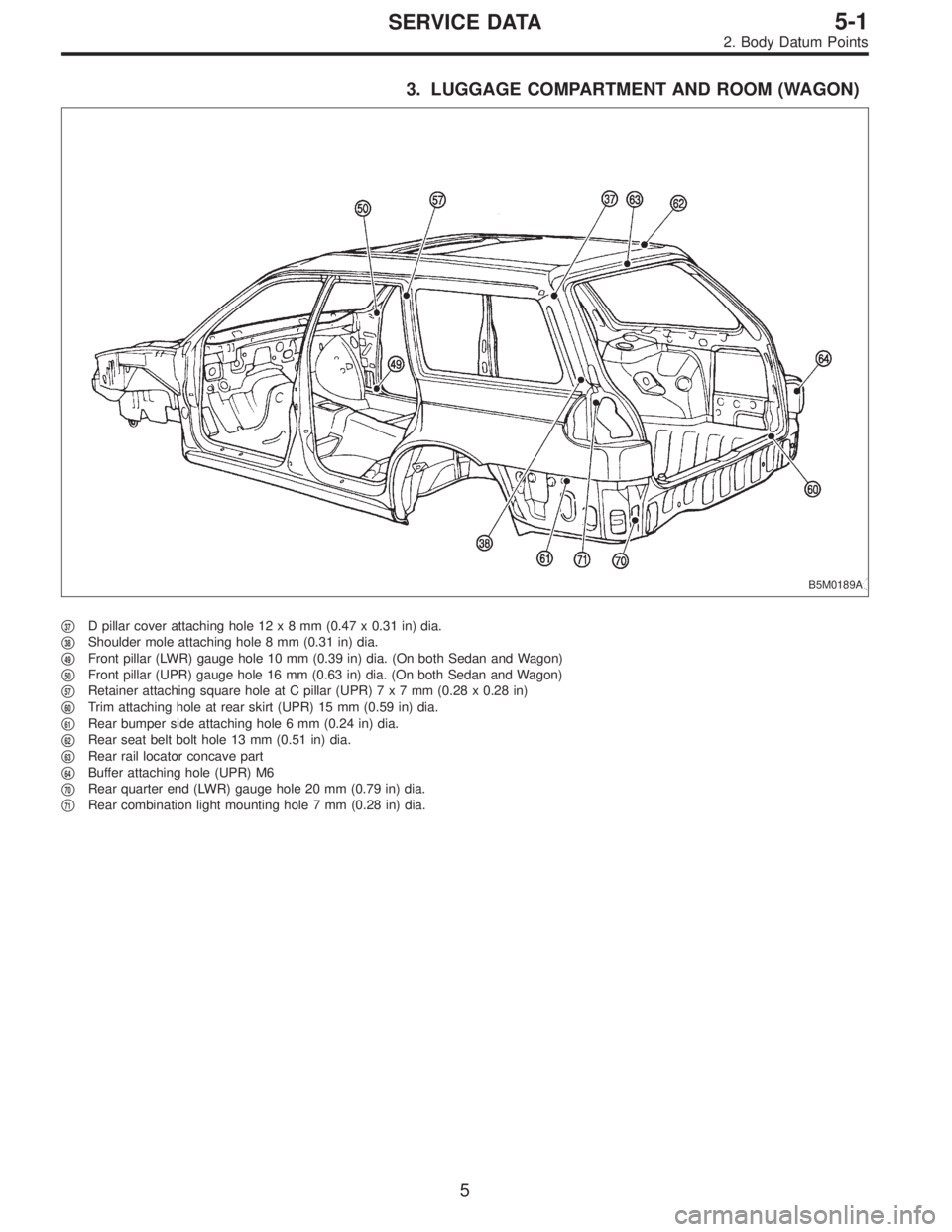
3. LUGGAGE COMPARTMENT AND ROOM (WAGON)
B5M0189A
�37D pillar cover attaching hole 12x8mm(0.47 x 0.31 in) dia.
�
38Shoulder mole attaching hole 8 mm (0.31 in) dia.
�
49Front pillar (LWR) gauge hole 10 mm (0.39 in) dia. (On both Sedan and Wagon)
�
50Front pillar (UPR) gauge hole 16 mm (0.63 in) dia. (On both Sedan and Wagon)
�
57Retainer attaching square hole at C pillar (UPR)7x7mm(0.28 x 0.28 in)
�
60Trim attaching hole at rear skirt (UPR) 15 mm (0.59 in) dia.
�
61Rear bumper side attaching hole 6 mm (0.24 in) dia.
�
62Rear seat belt bolt hole 13 mm (0.51 in) dia.
�
63Rear rail locator concave part
�
64Buffer attaching hole (UPR) M6
�
70Rear quarter end (LWR) gauge hole 20 mm (0.79 in) dia.
�
71Rear combination light mounting hole 7 mm (0.28 in) dia.
5
5-1SERVICE DATA
2. Body Datum Points
Page 1627 of 3342
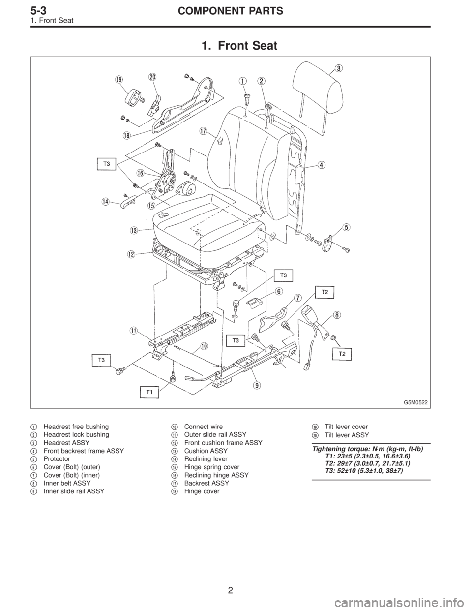
1. Front Seat
G5M0522
�1Headrest free bushing
�
2Headrest lock bushing
�
3Headrest ASSY
�
4Front backrest frame ASSY
�
5Protector
�
6Cover (Bolt) (outer)
�
7Cover (Bolt) (inner)
�
8Inner belt ASSY
�
9Inner slide rail ASSY�
10Connect wire
�
11Outer slide rail ASSY
�
12Front cushion frame ASSY
�
13Cushion ASSY
�
14Reclining lever
�
15Hinge spring cover
�
16Reclining hinge ASSY
�
17Backrest ASSY
�
18Hinge cover�
19Tilt lever cover
�
20Tilt lever ASSY
Tightening torque: N⋅m (kg-m, ft-lb)
T1: 23±5 (2.3±0.5, 16.6±3.6)
T2: 29±7 (3.0±0.7, 21.7±5.1)
T3: 52±10 (5.3±1.0, 38±7)
2
5-3COMPONENT PARTS
1. Front Seat
Page 1630 of 3342
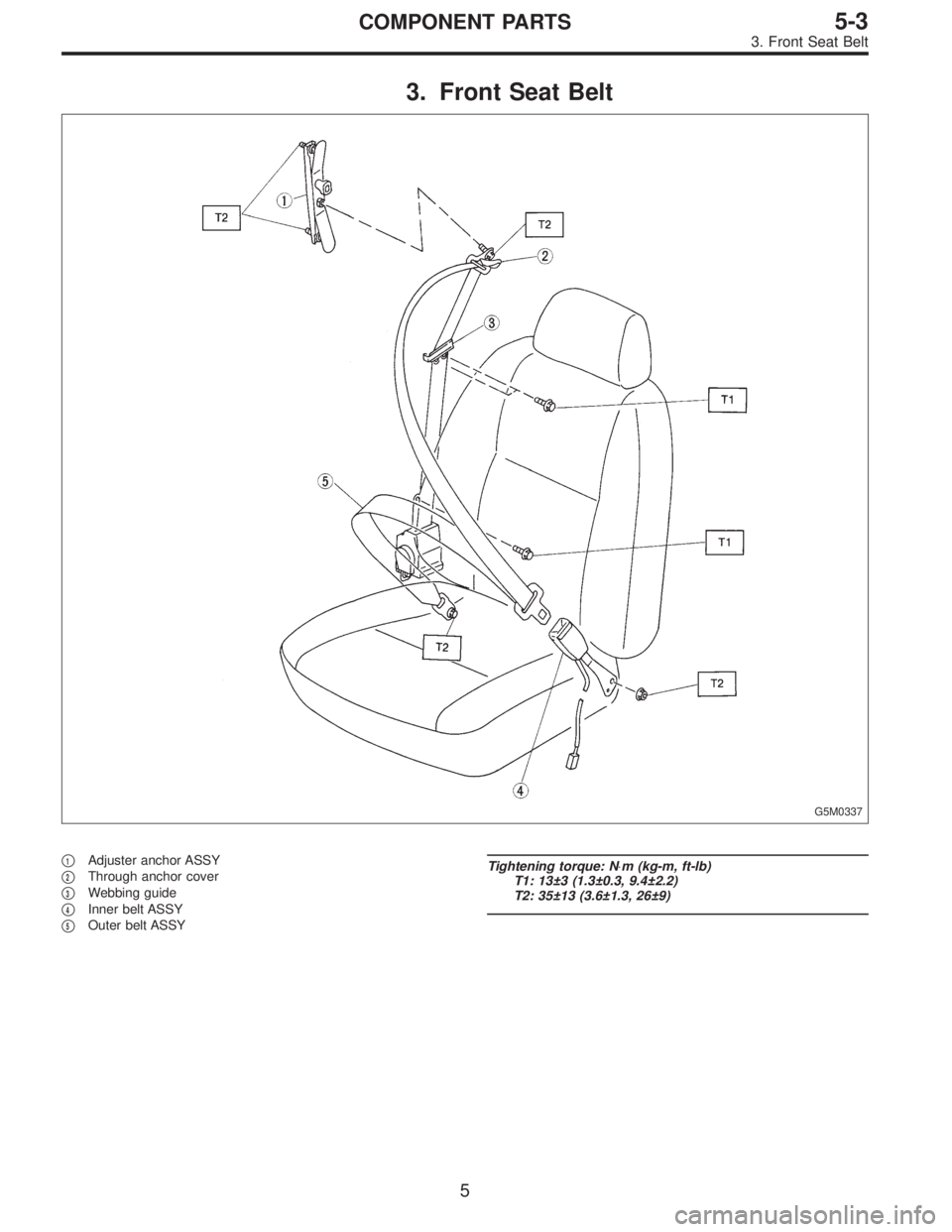
3. Front Seat Belt
G5M0337
�1Adjuster anchor ASSY
�
2Through anchor cover
�
3Webbing guide
�
4Inner belt ASSY
�
5Outer belt ASSY
Tightening torque: N⋅m (kg-m, ft-lb)
T1: 13±3 (1.3±0.3, 9.4±2.2)
T2: 35±13 (3.6±1.3, 26±9)
5
5-3COMPONENT PARTS
3. Front Seat Belt
Page 1631 of 3342
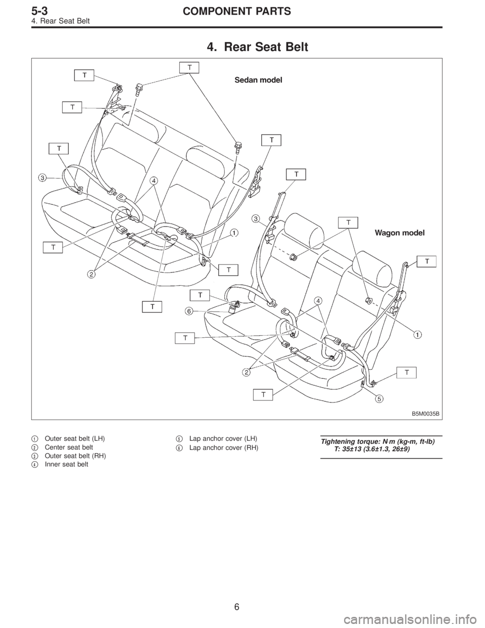
4. Rear Seat Belt
B5M0035B
�1Outer seat belt (LH)
�
2Center seat belt
�
3Outer seat belt (RH)
�
4Inner seat belt�
5Lap anchor cover (LH)
�
6Lap anchor cover (RH)Tightening torque: N⋅m (kg-m, ft-lb)
T: 35±13 (3.6±1.3, 26±9)
6
5-3COMPONENT PARTS
4. Rear Seat Belt
Page 1636 of 3342
 Remove bolts securing hinges (located at front of seat)
to body.
2) Pull strap (located in middle rear portion of cushion) to
release lock. Lift cushion out and away from bod")
G5M0350
2. WAGON MODEL
1) Remove bolts securing hinges (located at front of seat)
to body.
2) Pull strap (located in middle rear portion of cushion) to
release lock. Lift cushion out and away from body.
3) Pull knobs (located at each side of backrest’s upper
portion) up to release lock, and fold backrest all the way
forward.
B5M0333A
4) Remove the bolt�1and then remove backrest. (LH
side)
5) Remove the bolt�
2and then remove backrest (RH side)
from hinge bracket�
3.
G5M0348
G5M0345
B: INSTALLATION
1. SEDAN MODEL
1) Before installing backrest, ensure that trim panel, insu-
lator and seat belt are properly installed.
2) Transfer outer seat belt webbing to front of backrest and
fold backrest forward. Attach seat wire to upper hooks (2
places), and move pillow in the direction of“B”until back-
rest is aligned with lower mounting holes in body.
3) Engage backrest’s folding mechanism with striker.
4) Secure lower center and both sides of backrest to body
with bolts.
5) Slightly raise front section of cushion while pushing
down on cushion in the direction of“C”. With cushion held
in that position, attach rear section of cushion to hooks at
lower frame location.
6) Secure front of cushion to body with bolts.
CAUTION:
�Before installing seat, ensure that seat belt is placed
on cushion.
�Confirm that winding of three-point type seat belt
can operate regularly.
10
5-3SERVICE PROCEDURE
2. Rear Seat
![SUBARU LEGACY 1997 Service Repair Manual 9) Install belt cover.
10) Connect ground cable to negative terminal of battery.
11) Charge refrigerant. <Ref. to 4-7 [W708].>
B4M0095
12. Condenser
A: REMOVAL AND INSTALLATION
1) Disconnect battery n](/manual-img/17/57434/w960_57434-1487.png "SUBARU LEGACY 1997 Service Repair Manual 9) Install belt cover.
10) Connect ground cable to negative terminal of battery.
11) Charge refrigerant. <Ref. to 4-7 [W708].>
B4M0095
12. Condenser
A: REMOVAL AND INSTALLATION
1) Disconnect battery n")
![SUBARU LEGACY 1997 Service Repair Manual 9) Install belt cover.
10) Connect ground cable to negative terminal of battery.
11) Charge refrigerant. <Ref. to 4-7 [W708].>
B4M0095
12. Condenser
A: REMOVAL AND INSTALLATION
1) Disconnect battery n](/manual-img/17/57434/w960_57434-1488.png "SUBARU LEGACY 1997 Service Repair Manual 9) Install belt cover.
10) Connect ground cable to negative terminal of battery.
11) Charge refrigerant. <Ref. to 4-7 [W708].>
B4M0095
12. Condenser
A: REMOVAL AND INSTALLATION
1) Disconnect battery n")