Page 1712 of 3342
B6M0472A
5) Installing end frame
When assembling end frame to yoke, align notched portion
of end frame with lead wire grommet.
B6M0473A
6) Installing yoke
When installing yoke to magnetic switch, align notch of
yoke with protrusion of magnetic switch.
G6M0095
2. Generator
A: REMOVAL AND INSTALLATION
1) Disconnect battery ground cable.
G2M0088
2) Disconnect connector and terminal from generator.
G2M0286
3) Remove V-belt cover.
4) Remove front side V-belt.
16
6-1SERVICE PROCEDURE
1. Starter - 2. Generator
Page 1713 of 3342
G2M0090
5) Remove bolts which install generator onto bracket.
G2M0090
6) Installation is in the reverse order of removal.
CAUTION:
Check and adjust V-belt tension.
B6M0476A
B: DISASSEMBLY
1) Heat the portion�Aof rear cover to 50°C (122°F) with
heater drier.
G6M0065
2) Remove the four through bolts. Then insert the tip of a
flat-head screwdriver into the gap between the stator core
and front bracket. Pry then apart to disassemble.
G6M0066
3) Hold rotor with a vise and remove pulley nut.
17
6-1SERVICE PROCEDURE
2. Generator
Page 1736 of 3342
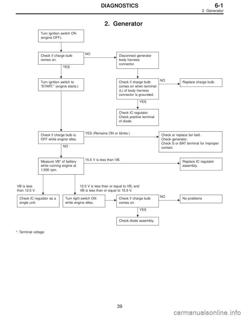
2. Generator
Turn ignition switch ON
(engine OFF).
Check if charge bulb
comes on.
YES
�NO
Disconnect generator
body harness
connector.
Turn ignition switch to
“START.”(engine starts.)Check if charge bulb
comes on when terminal
(L) of body harness
connector is grounded.
YES
�NO
Replace charge bulb.
Check IC regulator.
Check positive terminal
of diode.
Check if charge bulb is
OFF while engine idles.
NO
�YES (Remains ON or blinks.)
Check or replace fan belt.
Check generator.
Check S or BAT terminal for improper
contact.
Measure VB* of battery
while running engine at
1,500 rpm.�15.5 V is less than VB.
Replace IC regulator
assembly.
VB is less
than 12.5 V.12.5 V is less than or equal to VB, and
VB is less than or equal to 15.5 V.
Check IC regulator as a
single unit.
Turn light switch ON
while engine idles.�Check if charge bulb
comes on.
YES
�NO
No problems
Check diode assembly.
*: Terminal voltage
�
��
�
�
�
��
�
39
6-1DIAGNOSTICS
2. Generator
Page 1737 of 3342
, 100 minutes (AT)
Cold cranking ampere 430 amperes (MT), 490 amperes (AT)
Fuse10 A, 15 A, 20 A
Combination
meterSpeedometer")
1. Body Electrical
A: SPECIFICATIONS
BatteryReserve capacity 82 minutes (MT), 100 minutes (AT)
Cold cranking ampere 430 amperes (MT), 490 amperes (AT)
Fuse10 A, 15 A, 20 A
Combination
meterSpeedometer Electric pulse type
Tachometer Electric impulse type
Water temperature gauge Thermistor cross coil type
Fuel gauge Resistance cross coil type
Charge indicator light 12 V—1.4 W
Brake fluid level warning/parking brake indicator light 12 V—1.4 W
AT oil temperature warning light (AWD only) 12 V—1.4 W
ABS warning light 12 V—1.4 W
CHECK ENGINE warning light
(Malfunction indicator lamp)12 V—1.4 W
Oil pressure warning light 12 V—1.4 W
AIRBAG system warning light 12 V—1.4 W
Low fuel warning light 12 V—3W
FWD indicator light 12 V—1.4 W
TCS warning light 12 V—1.4 W
TCS indicator light 12 V—1.4 W
Turn signal indicator light 12 V—1.4 W (2 pieces)
Seat belt warning light 12 V—1.4 W
Door open warning light 12 V—1.4 W (5 pieces)
Headlight beam indicator light 12 V—1.4 W
Meter illumination light12 V—3 W (2 pieces)
12 V—3.4 W (4 pieces)
Headlight 12 V—60/55 W (Halogen)
Front clearance light 12 V—5W
Turn signal lightFront 12 V—21 W
Rear 12 V—21 W
Tail/Stop light 12 V—5/21 W
Back-up light 12 V—21 W
High-mount stop light12 V—18 W (SEDAN), 12 V—13 W
(WAGON)
License plate light 12 V—5W
Room light 12 V—8W
Trunk room light (SEDAN) 12 V—5W
Luggage room light (WAGON) 12 V—5W
Spot light 12 V—8 W (2 pieces)
Glove box light 12 V—3.4 W
Ash tray illumination light 12 V—1.7 W
Selector lever illumination light (AT model) 12 V—1.7 W
2
6-2SPECIFICATIONS
1. Body Electrical
Page 1776 of 3342
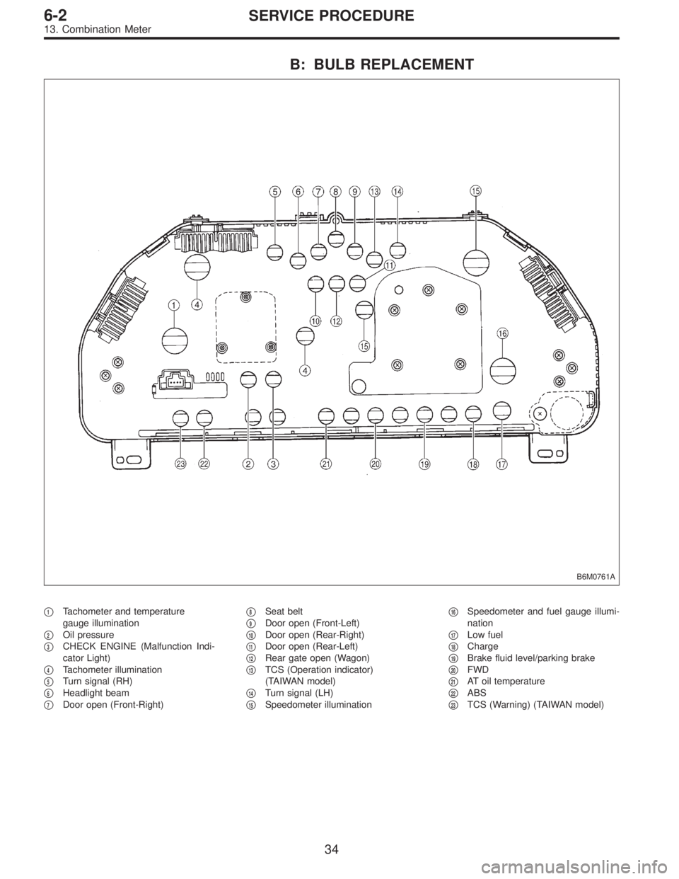
B: BULB REPLACEMENT
B6M0761A
�1Tachometer and temperature
gauge illumination
�
2Oil pressure
�
3CHECK ENGINE (Malfunction Indi-
cator Light)
�
4Tachometer illumination
�
5Turn signal (RH)
�
6Headlight beam
�
7Door open (Front-Right)�
8Seat belt
�
9Door open (Front-Left)
�
10Door open (Rear-Right)
�
11Door open (Rear-Left)
�
12Rear gate open (Wagon)
�
13TCS (Operation indicator)
(TAIWAN model)
�
14Turn signal (LH)
�
15Speedometer illumination�
16Speedometer and fuel gauge illumi-
nation
�
17Low fuel
�
18Charge
�
19Brake fluid level/parking brake
�
20FWD
�
21AT oil temperature
�
22ABS
�
23TCS (Warning) (TAIWAN model)
34
6-2SERVICE PROCEDURE
13. Combination Meter
Page 2068 of 3342
10AI7
GROUP OF #3 AND #4 CYLINDERS
: Are there faults in #3 and #4 cylinders?
NOTE:
�Check the following items.
�Spark plugs
�Fuel injectors
�Ignition coil
�If no abnormal is discovered, check for“D: IGNITION
CONTROL SYSTEM”of #3 and #4 cylinders side.
2-7 [T8D0].>
: Repair or replace faulty parts.
: Go to step10AI11.
10AI8
GROUP OF #1 AND #3 CYLINDERS
: Are there faults in #1 and #3 cylinders?
NOTE:
Check the following items.
�Spark plugs
�Fuel injectors
�Skipping timing belt teeth
: Repair or replace faulty parts.
: Go to step10AI11.
217
2-7ON-BOARD DIAGNOSTICS II SYSTEM
10. Diagnostic Chart with Trouble Code for LHD Vehicles
Page 2069 of 3342
10AI9
GROUP OF #2 AND #4 CYLINDERS
: Are there faults in #2 and #4 cylinders?
NOTE:
Check the following items.
�Spark plugs
�Fuel injectors
�Skipping timing belt teeth
: Repair or replace faulty parts.
: Go to step10AI11.
10AI10
THE CYLINDER AT RANDOM
: Is the engine idle rough?
: Go to step10AI11.
: Go to DTC P0170.
and [T10T5].>
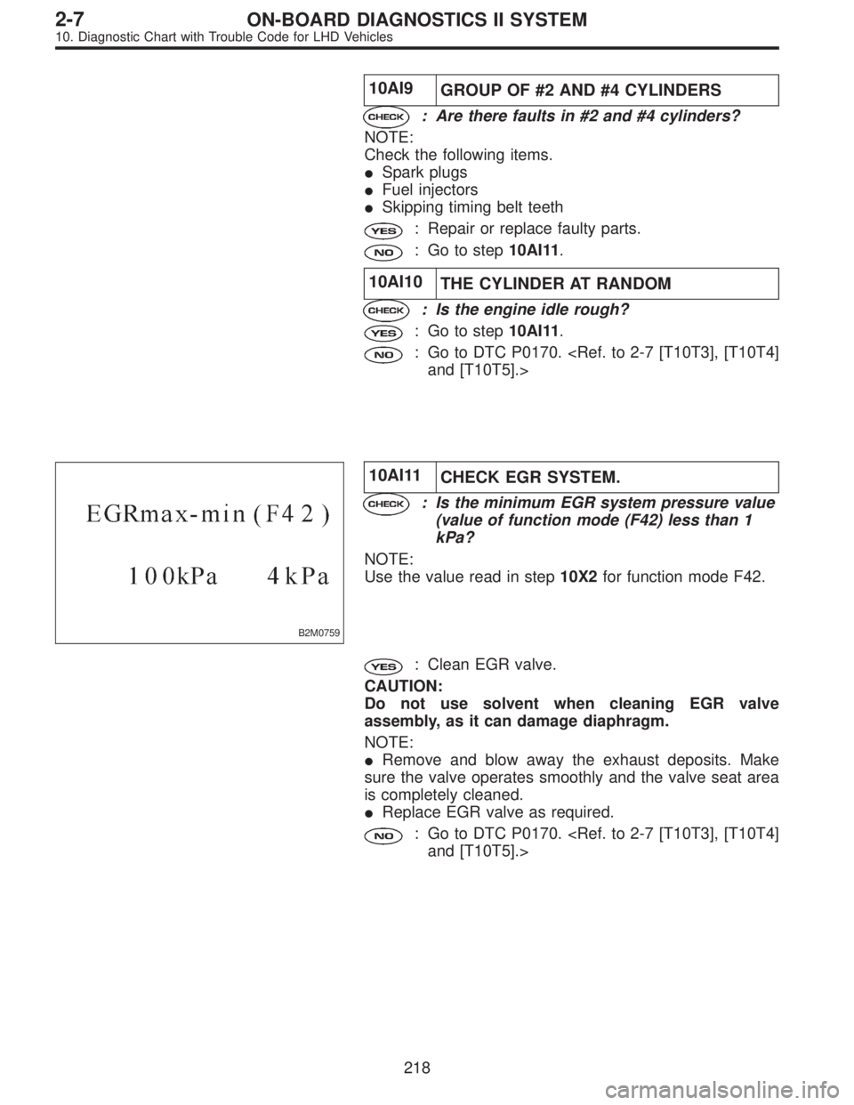
B2M0759
10AI11
CHECK EGR SYSTEM.
: Is the minimum EGR system pressure value
(value of function mode (F42) less than 1
kPa?
NOTE:
Use the value read in step10X2for function mode F42.
: Clean EGR valve.
CAUTION:
Do not use solvent when cleaning EGR valve
assembly, as it can damage diaphragm.
NOTE:
�Remove and blow away the exhaust deposits. Make
sure the valve operates smoothly and the valve seat area
is completely cleaned.
�Replace EGR valve as required.
: Go to DTC P0170.
and [T10T5].>
218
2-7ON-BOARD DIAGNOSTICS II SYSTEM
10. Diagnostic Chart with Trouble Code for LHD Vehicles
Page 3190 of 3342
 When working under a vehicle which is jacked-up,
always be sure to use safety stands.
2) The parking brake m")
3. Working Precautions
1. PRECAUTIONS WHEN WORKING WITH THE
PARTS MOUNTED ON THE VEHICLE
1) When working under a vehicle which is jacked-up,
always be sure to use safety stands.
2) The parking brake must always be applied during work-
ing. Also, in automatic transmission vehicles, keep the
select lever set to the P (Parking) range.
3) Be sure the workshop is properly ventilated when run-
ning the engine. Further, be careful not to touch the belt or
fan while the engine is operating.
4) Be careful not to touch hot metal parts, especially the
radiator and exhaust system immediately after the engine
has been shut off.
2. PRECAUTIONS IN TROUBLE DIAGNOSIS AND
REPAIR OF ELECTRIC PARTS
1) The battery cable must be disconnected from the bat-
tery’s (�) terminal, and the ignition switch must be set to the
OFF position, unless otherwise required by the diagnos-
tics.
2) Securely fasten the wiring harness with clamps and
slips so that the harness does not interfere with the body
end parts or edges and bolts or screws.
3) When installing parts, be careful not to catch them on
the wiring harness.
G6M0212
4) When disconnecting a connector, do not pull the wires,
but pull while holding the connector body.
11
6-3WIRING DIAGRAM
3. Working Precautions
 Installing end frame
When assembling end frame to yoke, align notched portion
of end frame with lead wire grommet.
B6M0473A
6) Installing yoke
When installing yoke to magnetic switch, alig")
![SUBARU LEGACY 1997 Service Repair Manual G2M0090
5) Remove bolts which install generator onto bracket.
G2M0090
6) Installation is in the reverse order of removal.
CAUTION:
Check and adjust V-belt tension. <Ref. to 1-5 [01A0].>
B6M0476A
B: DI](/manual-img/17/57434/w960_57434-1712.png "SUBARU LEGACY 1997 Service Repair Manual G2M0090
5) Remove bolts which install generator onto bracket.
G2M0090
6) Installation is in the reverse order of removal.
CAUTION:
Check and adjust V-belt tension. <Ref. to 1-5 [01A0].>
B6M0476A
B: DI")