1997 SUBARU LEGACY tire type
[x] Cancel search: tire typePage 16 of 3342

BRAKES
44
Page
S
SPECIFICATIONS
AND
SERVICE
DATA
1
.
Brakes
C
COMPONENT
PARTS
...........
.
.
.
.....................
.
.
......
..
.
.
.
..........................
1
.
FrontDisc
Brake
2
.
Rear
Disc
Brake
3
.
Rear
Drum
Brake
4
.
Master
Cylinder
5
.
Brake
Booster
6
.
ABS
System
7
.
Hill
Holder
8
.
Parking
(Hand)
Brake
9
.
ABS/TCS
System
10
.
ABS
System(ABS
5
.3i
Type)
...
....
.
...
..........................
.
.
...
.
.............
W
SERVICE
PROCEDURE
...............
.
.
......
.
.
...
.
....................
.
.
.
.
.
.
...
.
...
.
.......
1
.
Front
Disc
Brake
2
.
Rear
Disc
Brake
3
.
Rear
Drum
Brake
4
.
Parking
Brake
(Rear
Disc
Brake)
5
.
Master
Cylinder
6
.
Brake
Booster
7
.
Brake
Hose
8
.
Hill
Holder
9
.
Parking
Brake
Lever
10
.
Parking
Brake
Cable
11
.
Air
Bleeding
(Without
TCS
model)
12
.
Brake
Fluid
Replacement
13
.
Proportioning
Valve
14
.
ABS
Sensor
15
.
Hydraulic
Unit
for
ABS
System
16
.
ABS
Control
Module
17
.
G
Sensor
for
ABS
System
18
.
Brake
Hose
and
Pipe
am
.
.
.....
.
.................................
.
.
...
.
.....
..
19
.
Air
Bleeding
(With
TCS
model)
20
.
Hydraulic
Unit
for
ABS/TCS
System
21
.
ABS/TCS
Control
Module
22
.
Hydraulic
Unit
for
ABS
System
(ABS
5
.3
Type)
23
.
ABS
Control
Module
(ABS
5
.3
Type)
24
.
G
Sensor
for
ABS
System
(ABS
5
.3
Type)
25
.
ABS
Control
Module
and
Hydraulic
Control
Unit
(ABSCM&H/U)
[ABS
5
.3i
Type]
.
.
.
.
.
.
.
...
.
.
.
.
.
..
.
.
...................................
.
...
.
.
.........
..........
26
.
ABS
Sensor
(ABS
5
.3i
Type)
....
...........................................
.
.
....
.
...
.
27
G
Sensor
(ABS
5
3i
T
e)
2
....
.2
....
.4
........
.
.
..
.4
....
..
.15
....
..
.15
yp
....
.
.
......
...
.
...................................
.
.
.
.
.......
.
.
.....
K
DIAGNOSTICS
1
.
Entire
BrakeSystem
2
.
Hill
Holder
PRECAUTION
FORSUPPLEMENTAL
RESTRAINT
SYSTEM
"AIRBAG"
The
Supplemental
Restraint
System
"Airbag"
helps
to
reduce
the
risk
or
severity
of
injury
to
the
driver
in
a
frontal
collision
.
The
Supplemental
Restraint
System
consists
of
an
airbag
module
(located
in
the
center
of
the
steer-
ing
wheel),sensors,
a
control
module,warning
light,
wiring
harness
and
roll
connector
.
Information
necessary
to
servicethe
safety
is
included
in
the"5-5
.
SUPPLEMENTAL
RESTRAINT
SYSTEM"
ofthis
Service
Manual
.
WARNING
:
"
To
avoid
rendering
the
Airbag
system
inoperative,
which
could
lead
to
personal
injury
or
death
in
the
event
of
a
severe
frontal
collision,
all
maintenance
must
be
performed
byan
authorized
SUBARU
dealer
.
"
Improper
maintenance,
including
incorrect
removal
and
installation
of
the
Airbag
system,
can
lead
to
personal
injury
caused
by
unintentional
activation
of
the
Airbag
system
.
"
All
Airbag
system
electrical
wiring
harnesses
and
connectors
are
covered
with
yellow
outer
insu-
lation
.
Do
not
use
electrical
test
equipment
on
any
circuit
relatedtothe
Supplemental
Restraint
System
"Airbag"
.
Page 31 of 3342
4-4d
[T1oo]
BRAKES
[ABS
5
.31
TYPE]
1
.
Supplemental
Restraint
System
"Airbag"
-
2
.
Pre-inspection
1
.
Supplemental
Restraint
System
"Airbag"
Airbagsystem
wiring
harness
is
routed
near
the
ABS
sensor,
ABS
control
module
and
hydraulic
control
unit
.
CAUTION
:
All
Airbag
system
wiring
harness
and
connectors
are
colored
yellow
.
Do
not
use
electrical
test
equipment
on
these
circuit
.
e
Be
careful
not
to
damage
Airbag
system
wiring
har-
ness
when
servicing
the
ABS
sensor,
ABS
control
mod-
ule
and
hydraulic
control
unit
.
2
.
Pre-inspection
Before
performing
diagnostics,
check
the
following
items
which
might
affect
ABS
problems
:
A
:
MECHANICAL
INSPECTION
1
.
POWER
SUPPLY
1)
Measure
battery
voltage
and
specific
gravity
of
electro-
lyte
.
Standard
voltage
:
12
V,
or
more
Specific
gravity
:
Above
1
.260
2)
Check
the
condition
of
the
main
and
other
fuses,
and
harnesses
and
connectors
.
Also
check
for
proper
ground-
ing
.
2
.
BRAKE
FLUID
1)
Check
brake
fluidlevel
.
2)
Check
brake
fluid
leakage
.
3
.
BRAKEDRAG
Check
brake
drag
.
<
Ref
.
to
4-4
[K100].*1
>
4
.
BRAKE
PADAND
ROTOR
Check
brake
padand
rotor
.
<
Ref
.
to
4-4
[K100].*1
>
5
.
TIRE
SPECIFICATIONS,
TIRE
WEARAND
AIR
PRESSURE
Check
tire
specifications,
tire
wear
and
air
pressure
.
<
Ref
.
to
4-2
[S1
A1
],
[S1
A2]
.*1
>
2
Page 32 of 3342
4-4d
[T1oo]
BRAKES
[ABS
5
.31
TYPE]
1
.
Supplemental
Restraint
System
"Airbag"
-
2
.
Pre-inspection
1
.
Supplemental
Restraint
System
"Airbag"
Airbagsystem
wiring
harness
is
routed
near
the
ABS
sensor,
ABS
control
module
and
hydraulic
control
unit
.
CAUTION
:
All
Airbag
system
wiring
harness
and
connectors
are
colored
yellow
.
Do
not
use
electrical
test
equipment
on
these
circuit
.
e
Be
careful
not
to
damage
Airbag
system
wiring
har-
ness
when
servicing
the
ABS
sensor,
ABS
control
mod-
ule
and
hydraulic
control
unit
.
2
.
Pre-inspection
Before
performing
diagnostics,
check
the
following
items
which
might
affect
ABS
problems
:
A
:
MECHANICAL
INSPECTION
1
.
POWER
SUPPLY
1)
Measure
battery
voltage
and
specific
gravity
of
electro-
lyte
.
Standard
voltage
:
12
V,
or
more
Specific
gravity
:
Above
1
.260
2)
Check
the
condition
of
the
main
and
other
fuses,
and
harnesses
and
connectors
.
Also
check
for
proper
ground-
ing
.
2
.
BRAKE
FLUID
1)
Check
brake
fluidlevel
.
2)
Check
brake
fluid
leakage
.
3
.
BRAKEDRAG
Check
brake
drag
.
<
Ref
.
to
4-4
[K100].*1
>
4
.
BRAKE
PADAND
ROTOR
Check
brake
padand
rotor
.
<
Ref
.
to
4-4
[K100].*1
>
5
.
TIRE
SPECIFICATIONS,
TIRE
WEARAND
AIR
PRESSURE
Check
tire
specifications,
tire
wear
and
air
pressure
.
<
Ref
.
to
4-2
[S1
A1
],
[S1
A2]
.*1
>
2
Page 43 of 3342
4-4d
[TSao]
BRAKES
[ABS
5
.3i
TYPE]
6
.
Diagnostics
Chart
for
On-board
Diagnosis
System
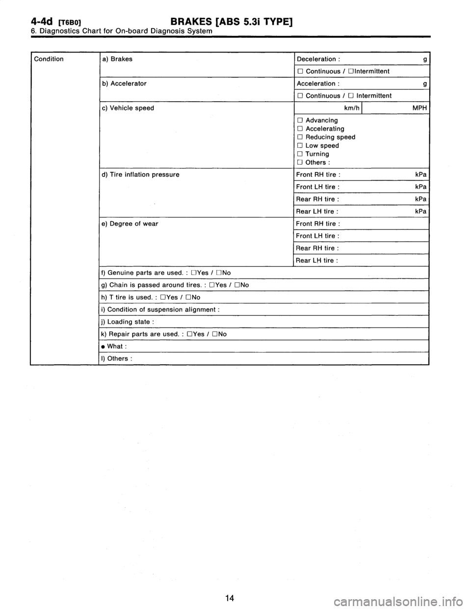
Condition
a)
Brakes
Deceleration
:
g
O
Continuous
/
Olntermittent
b)
AcceleratorAcceleration
:
g
O
Continuous
/
O
Intermittent
c)
Vehicle
speed
km/h
MPH
O
Advancing
O
Accelerating
O
Reducing
speed
O
Low
speed
O
Turning
D
Others
d)
Tire
inflation
pressure
Front
RH
tire
:
kPa
Front
LH
tire
:
kPa
Rear
RH
tire
:
kPa
Rear
LH
tire
:
kPa
e)
Degree
of
wear
Front
RH
tire
Front
LH
tire
Rear
RH
tire
Rear
LH
tire
f)
Genuine
parts
are
used
.:
Yes
/
ONo
g)
Chain
is
passed
around
tires
.:
Yes
/
DNo
h)
T
tire
is
used
.:
Yes
/
ONo
i)
Condition
of
suspension
alignment
j)
Loading
state
k)
Repair
parts
are
used
.
:
OYes
/
ONo
What
I)
Others
14
Page 62 of 3342
![SUBARU LEGACY 1997 Service Repair Manual
4-4d
[TSES1
BRAKES
[ABS
5
.31
TYPE]
8
.
Diagnostics
Chart
with
Trouble
Code
by
ABS
Warning
Light
G4M0700
I
Rear
Sensor
gap
G4M0701
8E8
I
CHECK
INSTALLATION
OFTONE
WHEEL
.
Tightening
torque
:
1](/manual-img/17/57434/w960_57434-61.png "SUBARU LEGACY 1997 Service Repair Manual
4-4d
[TSES1
BRAKES
[ABS
5
.31
TYPE]
8
.
Diagnostics
Chart
with
Trouble
Code
by
ABS
Warning
Light
G4M0700
I
Rear
Sensor
gap
G4M0701
8E8
I
CHECK
INSTALLATION
OFTONE
WHEEL
.
Tightening
torque
:
1")
4-4d
[TSES1
BRAKES
[ABS
5
.31
TYPE]
8
.
Diagnostics
Chart
with
Trouble
Code
by
ABS
Warning
Light
G4M0700
I
Rear
Sensor
gap
G4M0701
8E8
I
CHECK
INSTALLATION
OFTONE
WHEEL
.
Tightening
torque
:
13
f
3
N~m
(1.3
f
0
.3
kg-m,
9
f
2
.2
ft-Ib)
CHECK
:
Are
thetone
wheel
installation
bolts
tight-
ened
securely?
,rES
:
Go
to
step
8E9
.
No
:
Tightentone
wheel
installation
bolts
securely
.
8E9
I
CHECK
ABS
SENSOR
GAP
.
Measure
tone
wheel-to-pole
piece
gap
over
entire
perim-
eter
of
the
wheel
.
CHECK
;
Is
the
gap
within
the
specifications
shown
in
the
following
table?
Front
wheel
Rear
wheel
Specifications0
.9
-
1
.4
mm
(0
.035
-
0
.055
in)
0
.7
-
1
.2
mm
(0
.028
-
0
.047
in)
ves
:
Go
to
step
8E10
.
No
:
Adjust
the
gap
.
NOTE
:
Adjust
the
gap
using
spacers
(Part
No
.
26755AA000)
.
If
spacers
cannot
correct
the
gap,
replace
worn
sensor
or
worn
tone
wheel
.
8E10
CHECK
HUB
RUNOUT
.
Measure
hub
runout
.
CHECK
:
Is
the
runouf
less
than
0
.05
mm
(0
.0020
in)?
vES
:
Go
to
step
8E11
.
No
:
Repair
hub
.
36
Sensorgap
Page 66 of 3342
BRAKES
[ABS
5
.31
TYPE]
[T814]
4-4d
8
.
DiagnosticsChart
with
Trouble
Code
by
ABS
Warning
Light
G4M0700
G4M0701
811
1
CHECK
INSTALLATION
OF
ABS
SENSOR
.
Tightening
torque
:
32
f
10
N~m
(3
.3
+
1
.0
kg-m,
24
f
7
ft-Ib)
CHECK
:
Are
the
ABS
sensor
installation
bolts
tight-
ened
securely?
vES
:
Go
to
step
812
.
No
:
Tighten
ABS
sensor
installation
bolts
securely
.
812
1
CHECK
INSTALLATION
OF
TONEWHEEL
.l
Tightening
torque
:
13
f
3
N
"
m
(1.3
f
0
.3
kg-m,
9
f
2
.2
ft-Ib)
CHECK
:
Are
the
tone
wheel
installation
bolts
tight-
ened
securely?
vES
:
Go
to
step
813
.
No
:
Tightentone
wheel
installation
bolts
securely
.
$13
I
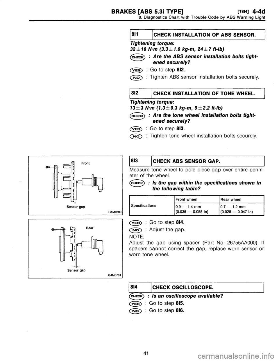
CHECK
ABS
SENSOR
GAP
.
Measure
tone
wheel
to
pole
piece
gap
over
entire
perim-
eterof
the
wheel
.
CHECK
:
Is
the
gap
within
the
specifications
shown
in
the
following
table?
Front
wheel
Rear
wheel
Specifications
0
.9
-
1
.4
mm
(0
.035
-
0
.055
in)
0
.7
-
1.2
mm
(0
.028
-
0
.047
in)
0
:
Go
to
step
814
.
No
:
Adjust
the
gap
.
NOTE
:
Adjustthe
gap
using
spacer
(Part
No
.
26755AA000)
.
If
spacers
cannot
correct
the
gap,
replace
worn
sensor
or
worn
tone
wheel
.
1814
1
CHECK
OSCILLOSCOPE
.
Is
an
oscilloscopeavailable?
,res
:
Go
to
step
815
.
No
:
Go
to
step
816
.
41
Sensor
gap
Sensor
gap
Page 73 of 3342
BRAKES
[ABS
5
.31
TYPE]
[T8J5]
4-4d
8
.
Diagnostics
Chart
with
Trouble
Code
by
ABS
Warning
Light
811
CHECK
FREELY'FOR
ALONG
TIME
.
TURNED
Check
if
the
wheels
havebeen
turned
freely
for
more
than
one
minute,
such
as
when
the
vehicle
is
jacked-up,
under
full-lock
corner-
ing
or
when
fire
is
not
in
contact
with
road
surface
.
The
ABS
is
normal
.
Erase
the
trouble
code
.
NOTE
:
When
the
wheels
turn
freely
for
along
time,
such
as
when
the
vehicle
is
towed
or
jacked-up,
or
when
steering
wheel
is
continuouslyturned
all
the
way,
this
trouble
code
may
sometimes
occur
.
No
:
Go
to
step
8,12
.
18J2
I
CHECK
TIRE
SPECIFICATIONS
.
CHECK
:
Are
the
fire
specifications
correct?
,res
:
Go
tostep8
.113
.
No
:
Replace
tire
.
18,13
1
CHECK
WEAR
OF
TIRE
.
CHECK
:
Is
the
fire
worn
excessively?
,res
:
Replace
tire
.
No
:
Go
tostep
8,14
.
18J4
I
CHECK
TIRE
PRESSURE
.
CHECK
:
Is
the
fire
pressure
correct?
,rES
:
Go
to
step
8J5
.
No
:
Adjust
tire
pressure
.
18,15
1
CHECK
INSTALLATION
OF
ABS
SENSOR
.
Tighteningtorque
:
32
f
10
N~m
(3
.3
f
1
.0
kg-m,
24
±
7
ft-Ib)
CHECK
:
Are
the
ABS
sensor
installation
bolts
tight-
ened
securely?
,res
:
Go
to
step
8J6
.
No
:
Tighten
ABS
sensor
installation
bolts
securely
.
49
Page 74 of 3342
![SUBARU LEGACY 1997 Service Repair Manual
4-4d
[TSJs1
BRAKES
[ABS
5
.31
TYPE]
8
.
Diagnostics
Chart
with
Trouble
Code
by
ABS
Warning
Light
G4M0700
I
G4M0701
CHECK
INSTALLATION
OF
TONE
WHEEL
.
Tightening
torque
:
13
f
3
N~m
(1.3
f
0
.3](/manual-img/17/57434/w960_57434-73.png "SUBARU LEGACY 1997 Service Repair Manual
4-4d
[TSJs1
BRAKES
[ABS
5
.31
TYPE]
8
.
Diagnostics
Chart
with
Trouble
Code
by
ABS
Warning
Light
G4M0700
I
G4M0701
CHECK
INSTALLATION
OF
TONE
WHEEL
.
Tightening
torque
:
13
f
3
N~m
(1.3
f
0
.3")
4-4d
[TSJs1
BRAKES
[ABS
5
.31
TYPE]
8
.
Diagnostics
Chart
with
Trouble
Code
by
ABS
Warning
Light
G4M0700
I
G4M0701
CHECK
INSTALLATION
OF
TONE
WHEEL
.
Tightening
torque
:
13
f
3
N~m
(1.3
f
0
.3
kg-m,
9
f
2
.2
ft-Ib)
CHECK
:
Are
the
tone
wheel
installation
bolts
tight-
ened
securely?
,res
:
Go
to
step
8J7
.
No
:
Tightentone
wheel
installation
bolts
securely
.
8J7
I
CHECK
ABS
SENSOR
GAP
.
Measure
tone
wheel
to
pole
piece
gap
over
entire
perim-
eter
of
the
wheel
.
CHECK
:
Is
the
gap
within
thespecifications
shown
in
the
following
table?
Front
wheel
Rear
wheel
Specifications
0
.9
-
1.4
mm
(0
.035
-
0
.055
in)
0
.7
-
1.2
mm
(0
.028
-
0
.047
in)
,
.ES
:
Go
tostep
8J8
.
No
:
Adjust
the
gap
.
NOTE
:
Adjustthe
gap
using
spacer
(Part
No
.
26755AA000)
.
If
spacers
cannot
correct
the
gap,
replace
worn
sensor
or
worn
tone
wheel
.
18,18
1
CHECK
OSCILLOSCOPE
.
Is
an
oscilloscopeavailable?
YES
:
Go
to
step
8J9
.
No
:
Go
to
step
8,1110
.
8J9
I
CHECK
ABS
SENSOR
SIGNAL
.
1)
Raise
all
four
wheels
of
ground
.
2)
Turn
ignition
switch
OFF
.
3)
Connect
theoscilloscope
to
the
connector
(F1)
or
con-
nector(B100)
.
4)
Turn
ignition
switch
ON
.
50
t
Sensor
gap
Sensor
gap