Page 26 of 3342
![SUBARU LEGACY 1997 Service Repair Manual
SERVICE
PROCEDURE
[W25D21
4-4
25
.
ABS
Control
Module
and
Hydraulic
Control
Unit
(ABSCM&H/U)
[ABS
5
.3i
Type]
Diagnosis
connector
--J
1
I`
--~
~
-
Diagnosis
terminals
3
terminal
6
terminal
-
SUBARU LEGACY 1997 Service Repair Manual
SERVICE
PROCEDURE
[W25D21
4-4
25
.
ABS
Control
Module
and
Hydraulic
Control
Unit
(ABSCM&H/U)
[ABS
5
.3i
Type]
Diagnosis
connector
--J
1
I`
--~
~
-
Diagnosis
terminals
3
terminal
6
terminal
-](/manual-img/17/57434/w960_57434-25.png)
SERVICE
PROCEDURE
[W25D21
4-4
25
.
ABS
Control
Module
and
Hydraulic
Control
Unit
(ABSCM&H/U)
[ABS
5
.3i
Type]
Diagnosis
connector
--J
1
I`
--~
~
''-
Diagnosis
terminals
3
terminal
6
terminal
-
/
B4M0082D
D
:
ABS
SEQUENCE
CONTROL
1)
Under
the
ABS
sequence
control,
after
thehydraulic
unit
solenoid
valve
is
driven,
theoperation
of
thehydrau-
lic
unit
can
be
checked
by
means
of
the
brake
tester
or
pressure
gauge
.
2)
ABS
sequence
control
can
be
started
by
diagnosis
connector
or
select
monitor
.
1
.
OPERATIONAL
GUIDELINES
OF
THE
ABS
SEQUENCE
CONTROL
WITH
DIAGNOSIS
CONNECTOR
1)
Connect
diagnosis
terminals
to
terminals
No
.
3
andNo
.
6
of
the
diagnosis
connector
beside
driver's
seat
heater
unit
.
2)
Setthe
speed
of
all
wheels
at
4
km/h
(2
MPH)
or
less
.
3)
Turn
ignition
switch
OFF
.
4)
Within
0
.5
seconds
after
the
ABS
warning
light
goes
out,
depress
the
brake
pedal
and
hold
it
immediately
after
ignition
switch
is
turned
to
ON
.
CAUTION
:
Do
not
depress
the
clutch
pedal
.
NOTE
:
*
When
the
ignition
switch
is
setto
on,the
brake
pedal
must
not
be
depressed
.
Engine
must
not
operate
.
5)
After
completion
of
ABS
sequence
control,
turn
ignition
switch
OFF
.
2
.
OPERATIONAL
GUIDELINES
OF
THE
ABS
SEQUENCE
CONTROL
WITH
SELECT
MONITOR
NOTE
:
In
the
event
of
any
trouble,
the
sequence
control
may
not
be
operative
.
In
such
a
case,
activate
the
sequence
control,
referring
to
"OPERATIONAL
GUIDELINES
OF
THE
ABS
SEQUENCE
CONTROL
WITHDIAGNOSIS
CONNEC-
TOR
"
.
<
Ref
.
to
4-4
[W25D1],*10>
1)
Connect
select
monitor
to
data
link
connector
beside
driver's
seat
heater
unit
.
2)
Turn
ignition
switch
ON
.
3)
Put
select
monitor
to
ABS
mode
.
11
Page 1047 of 3342
1. Propeller Shaft
A: ON-CAR SERVICE
Check the following points with propeller shaft installed in
vehicle.
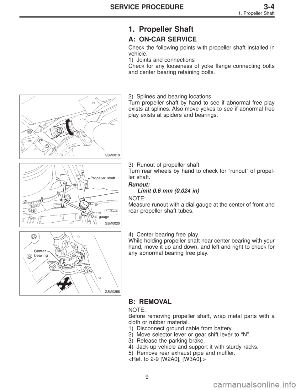
1) Joints and connections
Check for any looseness of yoke flange connecting bolts
and center bearing retaining bolts.
G3M0019
2) Splines and bearing locations
Turn propeller shaft by hand to see if abnormal free play
exists at splines. Also move yokes to see if abnormal free
play exists at spiders and bearings.
G3M0020
3) Runout of propeller shaft
Turn rear wheels by hand to check for“runout”of propel-
ler shaft.
Runout:
Limit 0.6 mm (0.024 in)
NOTE:
Measure runout with a dial gauge at the center of front and
rear propeller shaft tubes.
G3M0255
4) Center bearing free play
While holding propeller shaft near center bearing with your
hand, move it up and down, and left and right to check for
any abnormal bearing free play.
B: REMOVAL
NOTE:
Before removing propeller shaft, wrap metal parts with a
cloth or rubber material.
1) Disconnect ground cable from battery.
2) Move selector lever or gear shift lever to“N”.
3) Release the parking brake.
4) Jack-up vehicle and support it with sturdy racks.
5) Remove rear exhaust pipe and muffler.
9
3-4SERVICE PROCEDURE
1. Propeller Shaft
Page 1148 of 3342
E: INSTALLATION
1) Connect rear housing assembly and strut assembly.
CAUTION:
Use a new self-locking nut.
Tightening torque:
147±15 N⋅m (15±1.5 kg-m, 108±11 ft-lb)
2) Fit BJ (bell joint) to rear housing splines.
CAUTION:
Be careful not to damage inner oil seal lip.
G4M0245
3) Connect rear housing assembly to lateral link assembly.
CAUTION:
Use a new self-locking nut.
Tightening torque:
137±20 N⋅m (14±2 kg-m, 101±14 ft-lb)
G4M0246
4) Connect rear housing assembly to trailing link assem-
bly.
CAUTION:
Use a new self-locking nut.
Tightening torque:
98—127 N⋅m (10—13 kg-m, 72—94 ft-lb)
5) Connect parking brake cable to parking brake.
Disc brake: Perform steps 6) through 8).
6) Install disc rotor on rear housing assembly.
G4M0240
7) Install disc brake caliper on back plate.
Tightening torque:
52±6 N⋅m (5.3±0.6 kg-m, 38.3±4.3 ft-lb)
G4M0266
8) Install rear speed sensor to back plate (only vehicle
equipped with A.B.S.).
22
4-2SERVICE PROCEDURE
2. Rear Axle (AWD Model)
Page 1171 of 3342
5) Connect transverse link to housing.
Tightening torque (self-locking nut):
49±10 N⋅m (5.0±1.0 kg-m, 36±7 ft-lb)
CAUTION:
Use a new self-locking nut.
6) Install stabilizer bracket.
7) While depressing brake pedal, tighten axle nut to the
specified torque.
Tightening torque:
186±20 N⋅m (19±2 kg-m, 137±14 ft-lb)
CAUTION:
�Use a new axle nut.
�Always tighten axle nut before installing wheel on
vehicle. If wheel is installed and comes in contact with
ground when axle nut is loose, wheel bearings may be
damaged.
�Be sure to tighten axle nut to specified torque. Do
not overtighten it as this may damage wheel bearing.
8) After tightening axle nut, lock it securely.
G4M0293
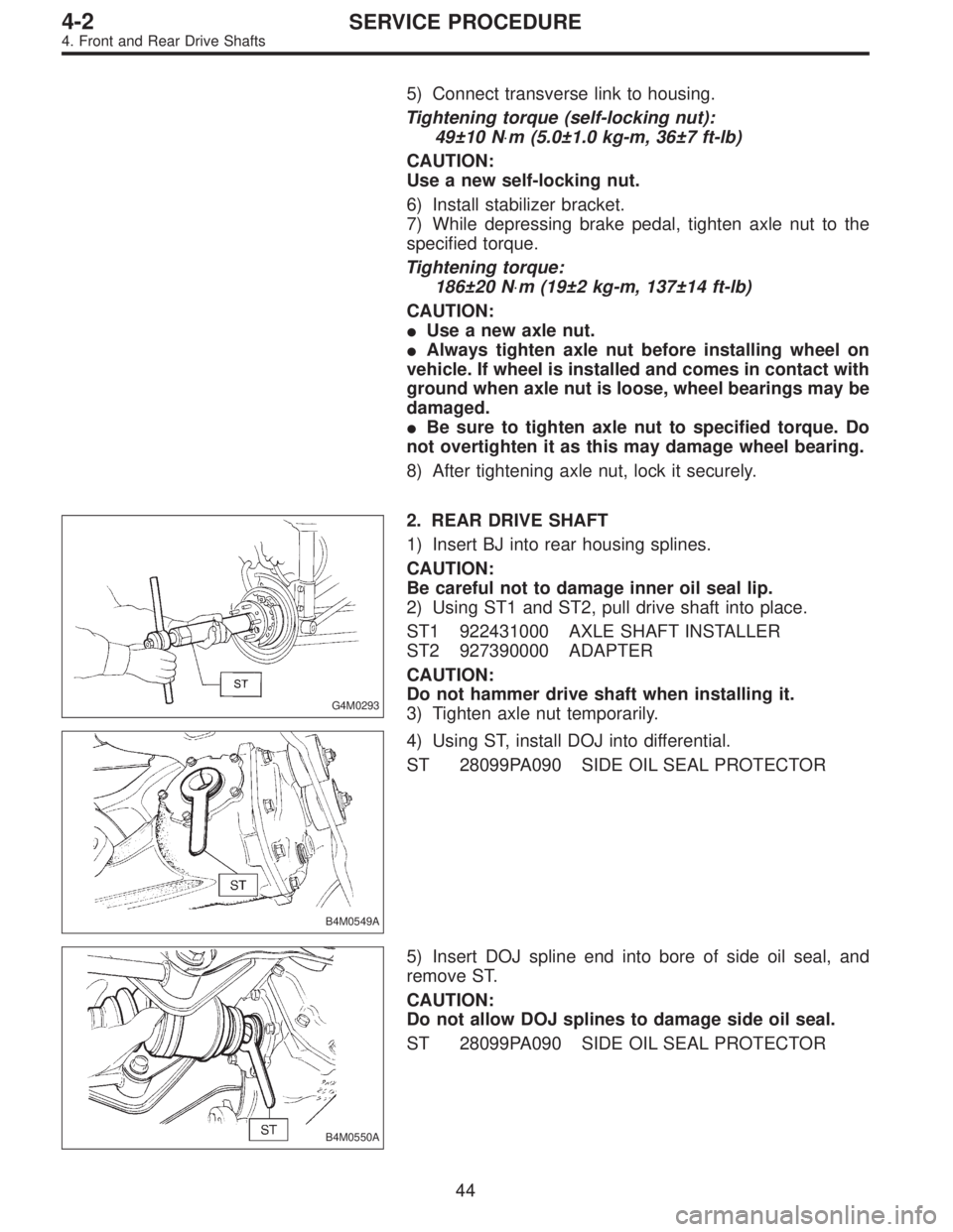
2. REAR DRIVE SHAFT
1) Insert BJ into rear housing splines.
CAUTION:
Be careful not to damage inner oil seal lip.
2) Using ST1 and ST2, pull drive shaft into place.
ST1 922431000 AXLE SHAFT INSTALLER
ST2 927390000 ADAPTER
CAUTION:
Do not hammer drive shaft when installing it.
3) Tighten axle nut temporarily.
B4M0549A
4) Using ST, install DOJ into differential.
ST 28099PA090 SIDE OIL SEAL PROTECTOR
B4M0550A
5) Insert DOJ spline end into bore of side oil seal, and
remove ST.
CAUTION:
Do not allow DOJ splines to damage side oil seal.
ST 28099PA090 SIDE OIL SEAL PROTECTOR
44
4-2SERVICE PROCEDURE
4. Front and Rear Drive Shafts
Page 1172 of 3342
G3M0050
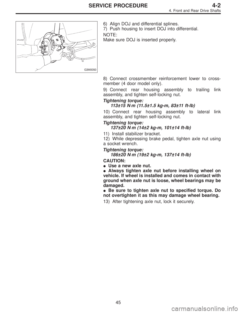
6) Align DOJ and differential splines.
7) Push housing to insert DOJ into differential.
NOTE:
Make sure DOJ is inserted properly.
8) Connect crossmember reinforcement lower to cross-
member (4 door model only).
9) Connect rear housing assembly to trailing link
assembly, and tighten self-locking nut.
Tightening torque:
113±15 N⋅m (11.5±1.5 kg-m, 83±11 ft-lb)
10) Connect rear housing assembly to lateral link
assembly, and tighten self-locking nut.
Tightening torque:
137±20 N⋅m (14±2 kg-m, 101±14 ft-lb)
11) Install stabilizer bracket.
12) While depressing brake pedal, tighten axle nut using
a socket wrench.
Tightening torque:
186±20 N⋅m (19±2 kg-m, 137±14 ft-lb)
CAUTION:
�Use a new axle nut.
�Always tighten axle nut before installing wheel on
vehicle. If wheel is installed and comes in contact with
ground when axle nut is loose, wheel bearings may be
damaged.
�Be sure to tighten axle nut to specified torque. Do
not overtighten it as this may damage wheel bearing.
13) After tightening axle nut, lock it securely.
45
4-2SERVICE PROCEDURE
4. Front and Rear Drive Shafts
Page 1175 of 3342
B4M0549A
2) Using ST, install DOJ into differential.
ST 28099PA090 SIDE OIL SEAL PROTECTOR
B4M0550A
3) Insert DOJ spline end into bore of side oil seal, and
remove ST.
CAUTION:
Do not allow DOJ splines to damage side oil seal.
ST 28099PA090 SIDE OIL SEAL PROTECTOR
G3M0050
4) Align DOJ and differential splines.
5) Push housing to insert DOJ into differential.
NOTE:
Make sure DOJ is inserted properly.
CAUTION:
Discard old self-locking nut. Replace with a new one.
6) Connect rear housing assembly to trailing link
assembly, and tighten self-locking nut.
7) Connect rear housing assembly to lateral link assembly,
and tighten self-locking nut.
8) Connect stabilizer link to lateral link.
9) Install crossmember reinforcement lower to crossmem-
ber (4 door model only).
10) Install A.B.S. sensor clamps and parking brake cable
bracket.
48
4-2SERVICE PROCEDURE
6. Replacement of Rear DOJ and BJ Boots
Page 1365 of 3342
D: ABS SEQUENCE CONTROL
1) Under the ABS sequence control, after the hydraulic
unit solenoid valve is driven, the operation of the hydraulic
unit can be checked by means of the brake tester or pres-
sure gauge.
2) ABS sequence control can be started by diagnosis con-
nector or select monitor.
B4M0082D
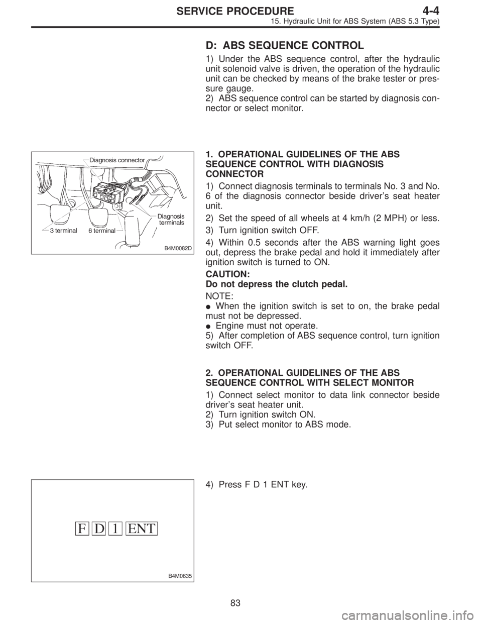
1. OPERATIONAL GUIDELINES OF THE ABS
SEQUENCE CONTROL WITH DIAGNOSIS
CONNECTOR
1) Connect diagnosis terminals to terminals No. 3 and No.
6 of the diagnosis connector beside driver’s seat heater
unit.
2) Set the speed of all wheels at 4 km/h (2 MPH) or less.
3) Turn ignition switch OFF.
4) Within 0.5 seconds after the ABS warning light goes
out, depress the brake pedal and hold it immediately after
ignition switch is turned to ON.
CAUTION:
Do not depress the clutch pedal.
NOTE:
�When the ignition switch is set to on, the brake pedal
must not be depressed.
�Engine must not operate.
5) After completion of ABS sequence control, turn ignition
switch OFF.
2. OPERATIONAL GUIDELINES OF THE ABS
SEQUENCE CONTROL WITH SELECT MONITOR
1) Connect select monitor to data link connector beside
driver’s seat heater unit.
2) Turn ignition switch ON.
3) Put select monitor to ABS mode.
B4M0635
4) PressFD1ENTkey.
83
4-4SERVICE PROCEDURE
15. Hydraulic Unit for ABS System (ABS 5.3 Type)
Page 1393 of 3342
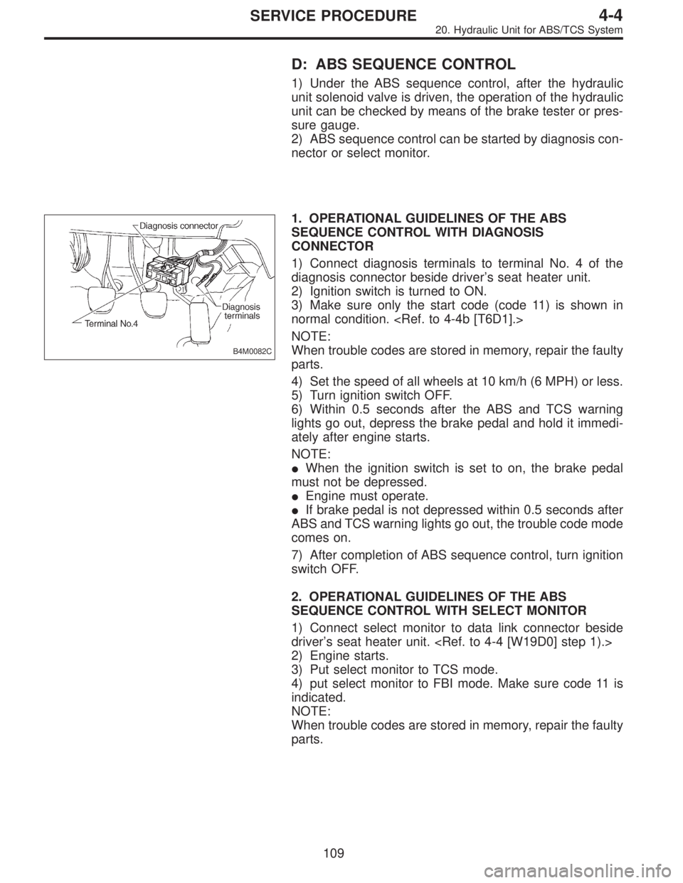
D: ABS SEQUENCE CONTROL
1) Under the ABS sequence control, after the hydraulic
unit solenoid valve is driven, the operation of the hydraulic
unit can be checked by means of the brake tester or pres-
sure gauge.
2) ABS sequence control can be started by diagnosis con-
nector or select monitor.
B4M0082C
1. OPERATIONAL GUIDELINES OF THE ABS
SEQUENCE CONTROL WITH DIAGNOSIS
CONNECTOR
1) Connect diagnosis terminals to terminal No. 4 of the
diagnosis connector beside driver’s seat heater unit.
2) Ignition switch is turned to ON.
3) Make sure only the start code (code 11) is shown in
normal condition.
NOTE:
When trouble codes are stored in memory, repair the faulty
parts.
4) Set the speed of all wheels at 10 km/h (6 MPH) or less.
5) Turn ignition switch OFF.
6) Within 0.5 seconds after the ABS and TCS warning
lights go out, depress the brake pedal and hold it immedi-
ately after engine starts.
NOTE:
�When the ignition switch is set to on, the brake pedal
must not be depressed.
�Engine must operate.
�If brake pedal is not depressed within 0.5 seconds after
ABS and TCS warning lights go out, the trouble code mode
comes on.
7) After completion of ABS sequence control, turn ignition
switch OFF.
2. OPERATIONAL GUIDELINES OF THE ABS
SEQUENCE CONTROL WITH SELECT MONITOR
1) Connect select monitor to data link connector beside
driver’s seat heater unit.
2) Engine starts.
3) Put select monitor to TCS mode.
4) put select monitor to FBI mode. Make sure code 11 is
indicated.
NOTE:
When trouble codes are stored in memory, repair the faulty
parts.
109
4-4SERVICE PROCEDURE
20. Hydraulic Unit for ABS/TCS System