Page 267 of 3342
1. Timing Belt
B2M0102A
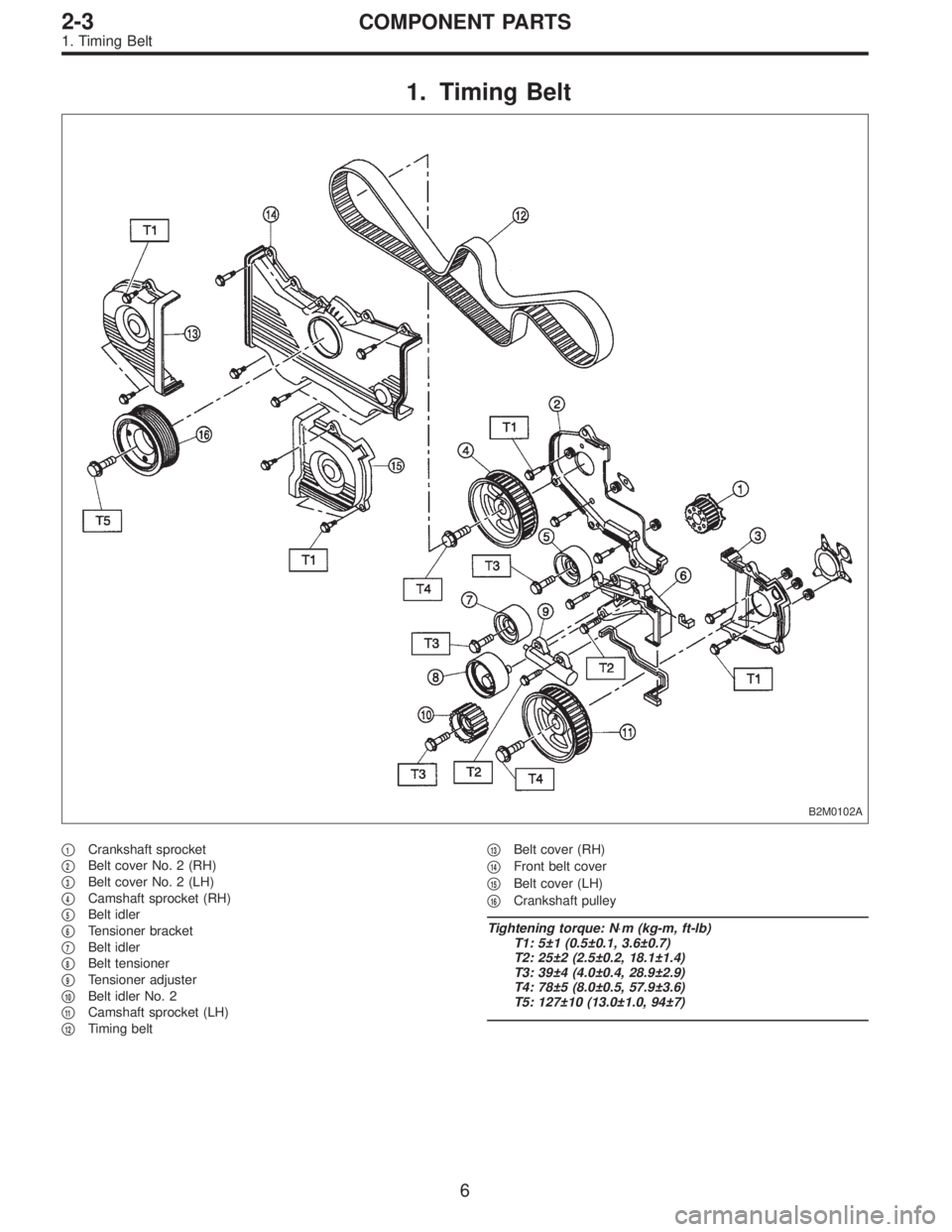
�1Crankshaft sprocket
�
2Belt cover No. 2 (RH)
�
3Belt cover No. 2 (LH)
�
4Camshaft sprocket (RH)
�
5Belt idler
�
6Tensioner bracket
�
7Belt idler
�
8Belt tensioner
�
9Tensioner adjuster
�
10Belt idler No. 2
�
11Camshaft sprocket (LH)
�
12Timing belt�
13Belt cover (RH)
�
14Front belt cover
�
15Belt cover (LH)
�
16Crankshaft pulley
Tightening torque: N⋅m (kg-m, ft-lb)
T1: 5±1 (0.5±0.1, 3.6±0.7)
T2: 25±2 (2.5±0.2, 18.1±1.4)
T3: 39±4 (4.0±0.4, 28.9±2.9)
T4: 78±5 (8.0±0.5, 57.9±3.6)
T5: 127±10 (13.0±1.0, 94±7)
6
2-3COMPONENT PARTS
1. Timing Belt
Page 272 of 3342
 Before disassembling engine, place it on ST3.
ST1 498457000 ENGINE STAND ADAPTER RH
ST2 498457100 ENGINE STAND ADAPTER LH
ST3 499817000 ENGINE STAND
2) All parts shou")
G2M0106
1. General Precautions
1) Before disassembling engine, place it on ST3.
ST1 498457000 ENGINE STAND ADAPTER RH
ST2 498457100 ENGINE STAND ADAPTER LH
ST3 499817000 ENGINE STAND
2) All parts should be thoroughly cleaned, paying special
attention to the engine oil passages, pistons and bearings.
3) Rotating parts and sliding parts such as piston, bearing
and gear should be coated with oil prior to assembly.
4) Be careful not to let oil, grease or coolant contact the
timing belt, clutch disc and flywheel.
5) All removed parts, if to be reused, should be reinstalled
in the original positions and directions.
6) Gaskets and lock washers must be replaced with new
ones. Liquid gasket should be used where specified to
prevent leakage.
7) Bolts, nuts and washers should be replaced with new
ones as required.
8) Even if necessary inspections have been made in
advance, proceed with assembly work while making
rechecks.
2. Hydraulic Lash Adjuster
A: INSPECTION
1) Disconnect blow-by hose from rocker cover.
2) Remove spark plug cap.
B2M0413A
3) Remove left and right rocker covers.
CAUTION:
Before removing left rocker cover, disconnect battery
cables and generator cable.
11
2-3SERVICE PROCEDURE
1. General Precautions - 2. Hydraulic Lash Adjuster
Page 273 of 3342
 Before disassembling engine, place it on ST3.
ST1 498457000 ENGINE STAND ADAPTER RH
ST2 498457100 ENGINE STAND ADAPTER LH
ST3 499817000 ENGINE STAND
2) All parts shou")
G2M0106
1. General Precautions
1) Before disassembling engine, place it on ST3.
ST1 498457000 ENGINE STAND ADAPTER RH
ST2 498457100 ENGINE STAND ADAPTER LH
ST3 499817000 ENGINE STAND
2) All parts should be thoroughly cleaned, paying special
attention to the engine oil passages, pistons and bearings.
3) Rotating parts and sliding parts such as piston, bearing
and gear should be coated with oil prior to assembly.
4) Be careful not to let oil, grease or coolant contact the
timing belt, clutch disc and flywheel.
5) All removed parts, if to be reused, should be reinstalled
in the original positions and directions.
6) Gaskets and lock washers must be replaced with new
ones. Liquid gasket should be used where specified to
prevent leakage.
7) Bolts, nuts and washers should be replaced with new
ones as required.
8) Even if necessary inspections have been made in
advance, proceed with assembly work while making
rechecks.
2. Hydraulic Lash Adjuster
A: INSPECTION
1) Disconnect blow-by hose from rocker cover.
2) Remove spark plug cap.
B2M0413A
3) Remove left and right rocker covers.
CAUTION:
Before removing left rocker cover, disconnect battery
cables and generator cable.
11
2-3SERVICE PROCEDURE
1. General Precautions - 2. Hydraulic Lash Adjuster
Page 277 of 3342
3. Timing Belt
A: REMOVAL
1. CRANKSHAFT PULLEY AND BELT COVER
G2M0107
G2M0108
1) Remove V-belt and A/C belt tensioner.
2) Remove pulley bolt. To lock crankshaft use ST.
ST 499977000 CRANKSHAFT PULLEY WRENCH
3) Remove crankshaft pulley.
4) Remove left side belt cover.
5) Remove right side belt cover.
6) Remove front belt cover.
15
2-3SERVICE PROCEDURE
3. Timing Belt
Page 278 of 3342
2. TIMING BELT
B2M0415A
G2M0616
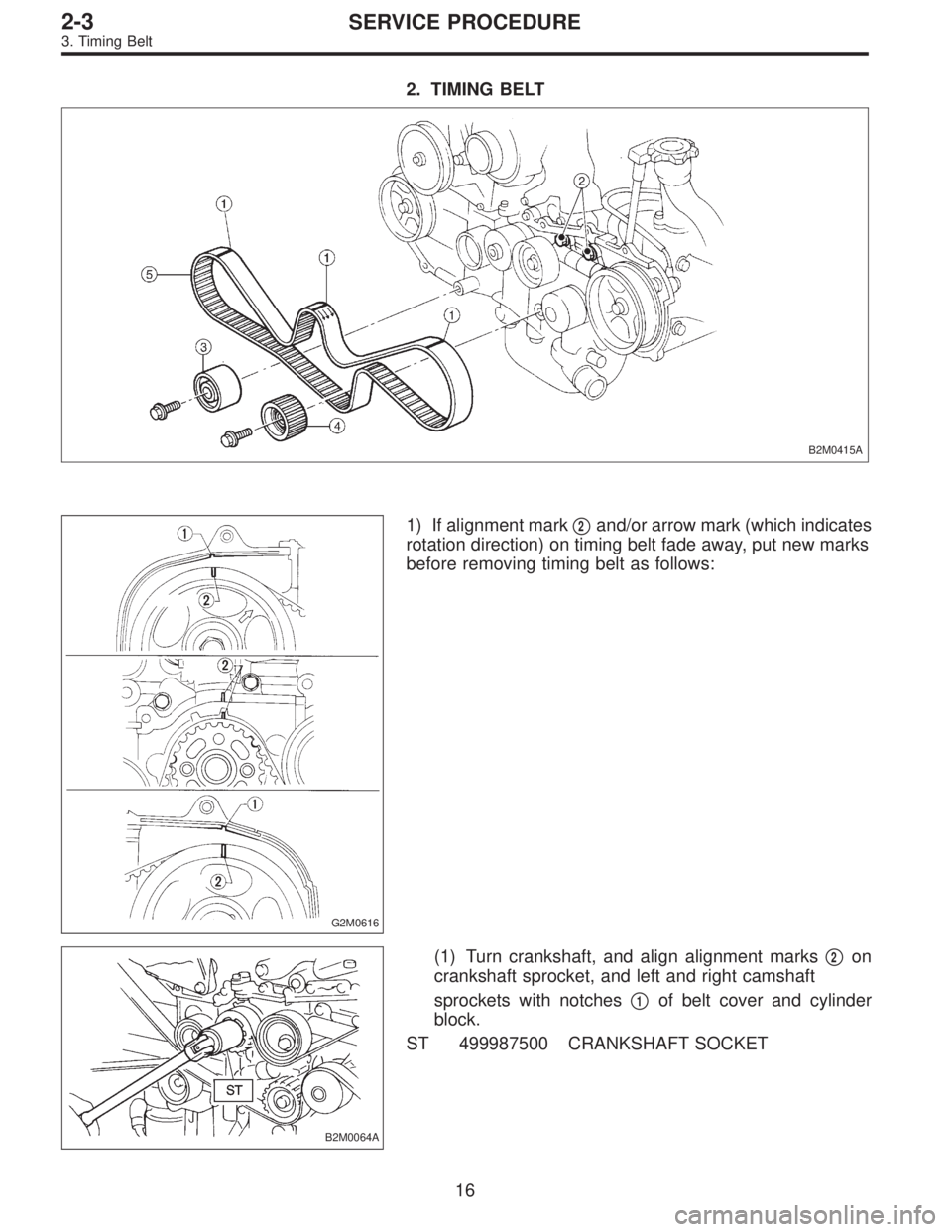
1) If alignment mark�2and/or arrow mark (which indicates
rotation direction) on timing belt fade away, put new marks
before removing timing belt as follows:
B2M0064A
(1) Turn crankshaft, and align alignment marks�2on
crankshaft sprocket, and left and right camshaft
sprockets with notches�
1of belt cover and cylinder
block.
ST 499987500 CRANKSHAFT SOCKET
16
2-3SERVICE PROCEDURE
3. Timing Belt
Page 279 of 3342
G2M0111
(2) Using white paint, put alignment and/or arrow
marks on timing belts in relation to the sprockets.
Z
1: 44 tooth length
Z
2: 40.5 tooth length
B2M0065
2) Loosen tensioner adjuster mounting bolts.
3) Remove belt idler.
4) Remove belt idler No. 2.
5) Remove timing belt.
6) Remove tensioner adjuster.
17
2-3SERVICE PROCEDURE
3. Timing Belt
Page 280 of 3342
3. BELT TENSIONER AND IDLER
G2M0112
1) Remove belt idler.
2) Remove belt tensioner and spacer.
3) Remove belt tensioner adjuster.
18
2-3SERVICE PROCEDURE
3. Timing Belt
Page 281 of 3342
4. SPROCKET
B2M0416A
G2M0114
1) Remove left side camshaft sprocket.
2) Remove right side camshaft sprocket. To lock camshaft
use ST.
ST 499207100 CAMSHAFT SPROCKET WRENCH
3) Remove crankshaft sprocket.
4) Remove left side belt cover No. 2.
5) Remove right side belt cover No. 2.
CAUTION:
Do not damage or lose the seal rubber when removing
belt covers.
6) Remove tensioner bracket.
19
2-3SERVICE PROCEDURE
3. Timing Belt
 Remove V-belt and A/C belt tensioner.
2) Remove pulley bolt. To lock crankshaft use ST.
ST 499977000 CRANKSHAFT PULLEY")
 Using white paint, put alignment and/or arrow
marks on timing belts in relation to the sprockets.
Z
1: 44 tooth length
Z
2: 40.5 tooth length
B2M0065
2) Loosen tensioner adjuster mounting")
 Remove belt idler.
2) Remove belt tensioner and spacer.
3) Remove belt tensioner adjuster.
18
2-3SERVICE PROCEDURE
3. Timing Belt")
 Remove left side camshaft sprocket.
2) Remove right side camshaft sprocket. To lock camshaft
use ST.
ST 499207100 CAMSHAFT SPROCKET WRENCH
3) Remove crankshaft sprocket")