Page 2194 of 3342
OBD0489
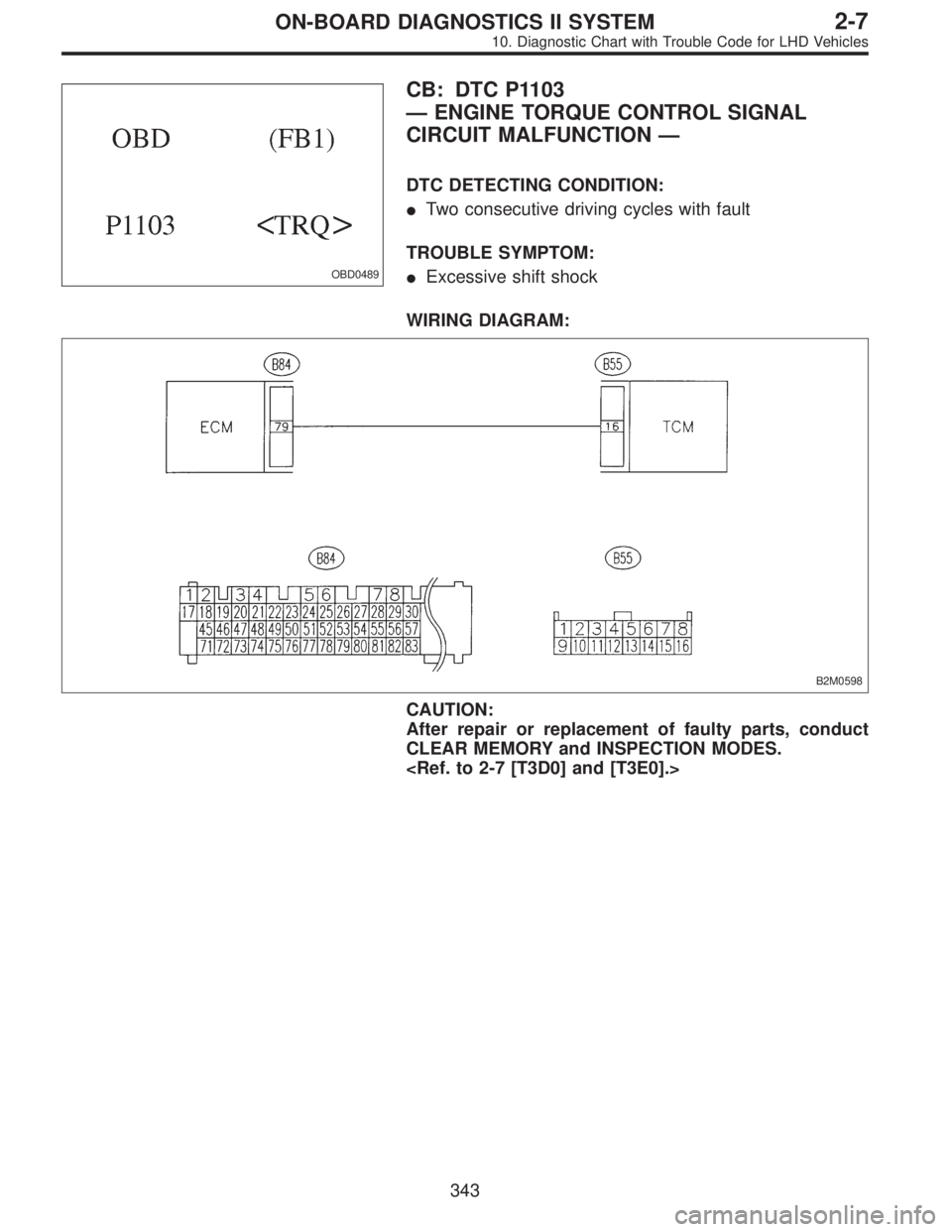
CB: DTC P1103
—ENGINE TORQUE CONTROL SIGNAL
CIRCUIT MALFUNCTION—
DTC DETECTING CONDITION:
�Two consecutive driving cycles with fault
TROUBLE SYMPTOM:
�Excessive shift shock
WIRING DIAGRAM:
B2M0598
CAUTION:
After repair or replacement of faulty parts, conduct
CLEAR MEMORY and INSPECTION MODES.
343
2-7ON-BOARD DIAGNOSTICS II SYSTEM
10. Diagnostic Chart with Trouble Code for LHD Vehicles
Page 2275 of 3342
Item Page
P0341 CAM
—R Camshaft position sensor circuit range/performance problem 463
P0400 EGR Exhaust gas recirculation flow malfunction 464
P0403 EGRSOL")
DTC
No.Abbreviation
(Subaru Select Monitor)Item Page
P0341 CAM
—R Camshaft position sensor circuit range/performance problem 463
P0400 EGR Exhaust gas recirculation flow malfunction 464
P0403 EGRSOL Exhaust gas recirculation circuit low input 465
P0420 CAT Catalyst system efficiency below threshold 466
P0440 EVAP Evaporative emission control system malfunction 467
P0441 CPC
—F Evaporative emission control system incorrect purge flow 468
P0443 CPC Evaporative emission control system purge control valve circuit low input 469
P0446 VCMSOL
—LO Evaporative emission control system vent control low input 470
P0451 TNKP
—F Evaporative emission control system pressure sensor range/performance problem 473
P0452 TNKP
—LOW Evaporative emission control system pressure sensor low input 474
P0453 TNKP
—HI Evaporative emission control system pressure sensor high input 479
P0461 FLVL
—R Fuel level sensor circuit range/performance problem 484
P0462 FLVL
—LOW Fuel level sensor circuit low input 486
P0463 FLVL
—HI Fuel level sensor circuit high input 492
P0500 VSP Vehicle speed sensor malfunction 497
P0505 ISC Idle control system malfunction 498
P0506 ISC
—RLOW Idle control system RPM lower than expected 499
P0507 ISC
—RHI Idle control system RPM higher than expected 500
P0600—Serial communication link malfunction 501
P0601 RAM Internal control module memory check sum error 502
P0703 ATBRK Brake switch input malfunction 503
P0705 ATRNG Transmission range sensor circuit malfunction 504
P0710 ATF Transmission fluid temperature sensor circuit malfunction 505
P0720 ATVSP Output speed sensor (vehicle speed sensor 1) circuit malfunction 506
P0725 ATNE Engine speed input circuit malfunction 507
P0731 ATGR1 Gear 1 incorrect ratio 508
P0732 ATGR2 Gear 2 incorrect ratio 508
P0733 ATGR3 Gear 3 incorrect ratio 508
P0734 ATGR4 Gear 4 incorrect ratio 508
P0740 ATLU
—F Torque converter clutch system malfunction 510
P0743 ATLU Torque converter clutch system electrical 511
P0748 ATPL Pressure control solenoid electrical 512
P0753 ATSFT1 Shift solenoid A electrical 513
P0758 ATSFT2 Shift solenoid B electrical 514
P0760 ATOVR
—F Shift solenoid C malfunction 515
P0763 ATOVR Shift solenoid C electrical 516
P1100 ST
—SWOFF Starter switch circuit low input 517
P1101 N
—SWOFF Neutral position switch circuit high input [AT vehicles] 518
P1102 BR Pressure sources switching solenoid valve circuit low input 519
P1103 TRQ Engine torque control signal circuit malfunction 520
P1120 ST
—SWON Starter switch circuit high input 521
P1121 N
—SWON Neutral position switch circuit low input [AT vehicles] 522
424
2-7ON-BOARD DIAGNOSTICS II SYSTEM
11. Diagnostic Chart with Trouble Code for RHD Vehicles
Page 2361 of 3342
B2M0661
BQ: DTC P0740
—TORQUE CONVERTER CLUTCH SYSTEM
MALFUNCTION—
WIRING DIAGRAM:
B2M1109
NOTE:
Check torque converter lock-up control system.
510
2-7ON-BOARD DIAGNOSTICS II SYSTEM
11. Diagnostic Chart with Trouble Code for RHD Vehicles
Page 2362 of 3342
B2M0662
BR: DTC P0743
—TORQUE CONVERTER CLUTCH SYSTEM
(DUTY SOLENOID B) ELECTRICAL—
WIRING DIAGRAM:
OBD0413
NOTE:
Check duty solenoid B circuit.
511
2-7ON-BOARD DIAGNOSTICS II SYSTEM
11. Diagnostic Chart with Trouble Code for RHD Vehicles
Page 2371 of 3342
OBD0489
CA: DTC P1103
—ENGINE TORQUE CONTROL SIGNAL
CIRCUIT MALFUNCTION—
WIRING DIAGRAM:
B2M0598
NOTE:
Check engine torque control signal circuit.
520
2-7ON-BOARD DIAGNOSTICS II SYSTEM
11. Diagnostic Chart with Trouble Code for RHD Vehicles
Page 2412 of 3342
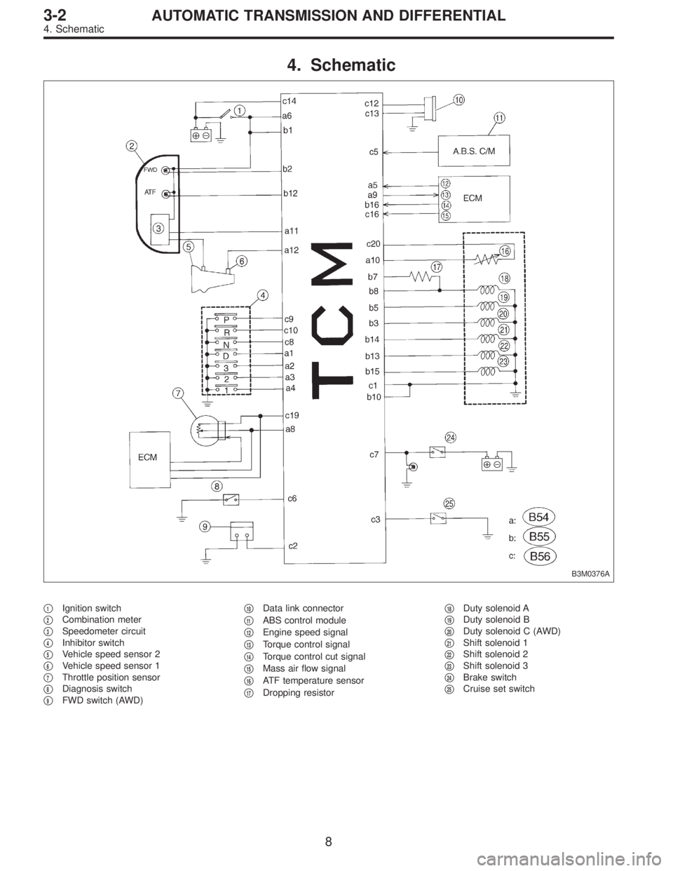
4. Schematic
B3M0376A
�1Ignition switch
�
2Combination meter
�
3Speedometer circuit
�
4Inhibitor switch
�
5Vehicle speed sensor 2
�
6Vehicle speed sensor 1
�
7Throttle position sensor
�
8Diagnosis switch
�
9FWD switch (AWD)�
10Data link connector
�
11ABS control module
�
12Engine speed signal
�
13Torque control signal
�
14Torque control cut signal
�
15Mass air flow signal
�
16ATF temperature sensor
�
17Dropping resistor�
18Duty solenoid A
�
19Duty solenoid B
�
20Duty solenoid C (AWD)
�
21Shift solenoid 1
�
22Shift solenoid 2
�
23Shift solenoid 3
�
24Brake switch
�
25Cruise set switch
8
3-2AUTOMATIC TRANSMISSION AND DIFFERENTIAL
4. Schematic
Page 2414 of 3342
Resistance to
body
(ohms)
Throttle position
sensorB54 8Throttle fully closed. 0.5±0.2
—
Throttle fully open. 4.6±0.3
Throttle positio")
ContentConnector
No.Terminal
No.Measuring conditionsVoltage
(V)Resistance to
body
(ohms)
Throttle position
sensorB54 8Throttle fully closed. 0.5±0.2
—
Throttle fully open. 4.6±0.3
Throttle position
sensor power
supplyB56 19Ignition switch ON
(With engine OFF)5.05±0.25—
ATF temperature
sensorB54 10ATF temperature 20°C(68°F) 3.45±0.55 2.1—2.9 k
ATF temperature 80°C (176°F) 1.2±0.2 275—375
Vehicle speed
sensor 1B54 12Vehicle stopped. 0
450—720
Vehicle speed at least 20 km/h (12
MPH)More than 1 (AC range)
Vehicle speed
sensor 2B56 11When vehicle is slowly moved at
least 2 meters (7ft).Less than 1)More than 9—
Engine speed
signalB54 5Ignition switch ON (with engine
OFF).More than 10.5
—
Ignition switch ON (with engine ON). 8—11
Cruise set signal B56 3When cruise control is set (SET
lamp ON).Less than 1
—
When cruise control is not set (SET
lamp OFF).More than 6.5
Torque control
signalB55 16 Ignition switch ON 5±1—
Torque control cut
signalB56 16 Ignition switch ON 6—9—
Mass air flow
signalB54 9 Engine idling after warm-up 0.5—1.2—
Shift solenoid 1 B55 141st or 4th gear More than 9
20—32
2nd or 3rd gear Less than 1
Shift solenoid 2 B55 131st or 2nd gear More than 9
20—32
3rd or 4th gear Less than 1
Shift solenoid 3 B55 15Select lever in“N”range (with
throttle fully closed).Less than 1
20—32
Select lever in“D”range (with
throttle fully closed).More than 9
Duty solenoid A B55 8Throttle fully closed (with engine
OFF) after warm-up.1.5—4.0
2.0—4.5
Throttle fully open (with engine
OFF) after warm-up.Less than 1
Dropping resistor B55 7Throttle fully closed (with engine
OFF) after warm-up.More than 8.5
12—18
Throttle fully open (with engine
OFF) after warm-up.Less than 1
Duty solenoid B B55 5When lock up occurs. More than 8.5
9—17
When lock up is released. Less than 0.5
Duty solenoid C
(AWD model only)B55 3Fuse on FWD switch More than 8.5
9—17 Fuse removed from FWD switch
(with throttle fully open and with
select lever in 1st gear).Less than 0.5
Sensor ground
line 1B54 7—0 Less than 1
Sensor ground
line 2B56 20—0 Less than 1
System ground
lineB56 1—0 Less than 1
Power system
ground lineB55 10—0 Less than 1
FWD switch
(AWD model only)B56 2Fuse removed. 6—9.1
—
Fuse installed. Less than 1
10
3-2AUTOMATIC TRANSMISSION AND DIFFERENTIAL
5. Transmission Control Module (TCM) I/O Signal
Page 2418 of 3342
Page
11 Duty solenoid ADetects open or shorted drive
circuit, as well as valve seizure.PLDTY 16
12 D")
D: LIST OF TROUBLE CODE
1. TROUBLE CODE
Trouble code Item Content of diagnosisAbbr.
(Select monitor)Page
11 Duty solenoid ADetects open or shorted drive
circuit, as well as valve seizure.PLDTY 16
12 Duty solenoid BDetects open or shorted drive
circuit, as well as valve seizure.LUDTY 20
13 Shift solenoid 3Detects open or shorted drive
circuit, as well as valve seizure.OVR 24
14 Shift solenoid 2Detects open or shorted drive
circuit, as well as valve seizure.SFT2 26
15 Shift solenoid 1Detects open or shorted drive
circuit, as well as valve seizure.SFT1 28
21 ATF temperature sensorDetects open or shorted input
signal circuit.ATFT 30
22 Mass air flow signalDetects open or shorted input
signal circuit.AFM 33
23 Engine speed signalDetects open or shorted input
signal circuit.EREV 35
24 Duty solenoid CDetects open or shorted drive
circuit, as well as valve seizure.4WDTY 37
25 Torque control signalDetects open or shorted input
signal circuit.TQ.CT 39
31 Throttle position sensorDetects open or shorted input
signal circuit.THV 41
32 Vehicle speed sensor 1Detects open or shorted input
signal circuit.VSP1 44
33 Vehicle speed sensor 2Detects open or shorted input
signal circuit.VSP2 48
14
3-2AUTOMATIC TRANSMISSION AND DIFFERENTIAL
6. Diagnostic Chart for On-board Diagnostic System
![SUBARU LEGACY 1997 Service Repair Manual B2M0661
BQ: DTC P0740
—TORQUE CONVERTER CLUTCH SYSTEM
MALFUNCTION—
WIRING DIAGRAM:
B2M1109
NOTE:
Check torque converter lock-up control system.
<Ref. to 2-7 [T10BQ0].>
510
2-7ON-BOARD DIAGNOSTICS](/manual-img/17/57434/w960_57434-2360.png "SUBARU LEGACY 1997 Service Repair Manual B2M0661
BQ: DTC P0740
—TORQUE CONVERTER CLUTCH SYSTEM
MALFUNCTION—
WIRING DIAGRAM:
B2M1109
NOTE:
Check torque converter lock-up control system.
<Ref. to 2-7 [T10BQ0].>
510
2-7ON-BOARD DIAGNOSTICS")
![SUBARU LEGACY 1997 Service Repair Manual B2M0662
BR: DTC P0743
—TORQUE CONVERTER CLUTCH SYSTEM
(DUTY SOLENOID B) ELECTRICAL—
WIRING DIAGRAM:
OBD0413
NOTE:
Check duty solenoid B circuit.
<Ref. to 2-7 [T10BR0].>
511
2-7ON-BOARD DIAGNOSTICS](/manual-img/17/57434/w960_57434-2361.png "SUBARU LEGACY 1997 Service Repair Manual B2M0662
BR: DTC P0743
—TORQUE CONVERTER CLUTCH SYSTEM
(DUTY SOLENOID B) ELECTRICAL—
WIRING DIAGRAM:
OBD0413
NOTE:
Check duty solenoid B circuit.
<Ref. to 2-7 [T10BR0].>
511
2-7ON-BOARD DIAGNOSTICS")
![SUBARU LEGACY 1997 Service Repair Manual OBD0489
CA: DTC P1103
—ENGINE TORQUE CONTROL SIGNAL
CIRCUIT MALFUNCTION—
WIRING DIAGRAM:
B2M0598
NOTE:
Check engine torque control signal circuit.
<Ref. to 2-7 [T10CB0].>
520
2-7ON-BOARD DIAGNOSTI](/manual-img/17/57434/w960_57434-2370.png "SUBARU LEGACY 1997 Service Repair Manual OBD0489
CA: DTC P1103
—ENGINE TORQUE CONTROL SIGNAL
CIRCUIT MALFUNCTION—
WIRING DIAGRAM:
B2M0598
NOTE:
Check engine torque control signal circuit.
<Ref. to 2-7 [T10CB0].>
520
2-7ON-BOARD DIAGNOSTI")