Page 2705 of 3342
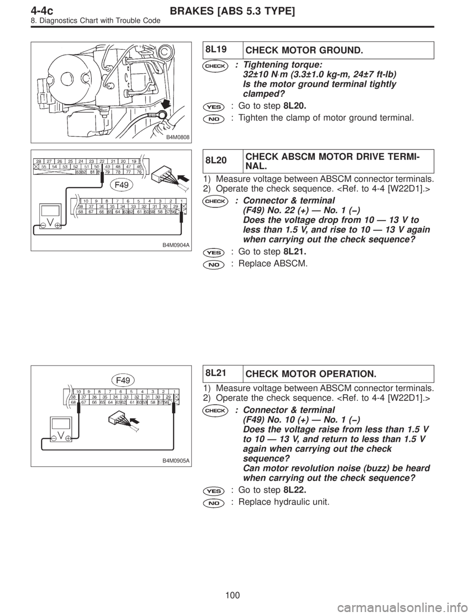
B4M0808
8L19
CHECK MOTOR GROUND.
: Tightening torque:
32±10 N⋅m (3.3±1.0 kg-m, 24±7 ft-lb)
Is the motor ground terminal tightly
clamped?
: Go to step8L20.
: Tighten the clamp of motor ground terminal.
B4M0904A
8L20CHECK ABSCM MOTOR DRIVE TERMI-
NAL.
1) Measure voltage between ABSCM connector terminals.
2) Operate the check sequence.
: Connector & terminal
(F49) No. 22 (+)—No.1(�)
Does the voltage drop from 10—13Vto
less than 1.5 V, and rise to 10—13 V again
when carrying out the check sequence?
: Go to step8L21.
: Replace ABSCM.
B4M0905A
8L21
CHECK MOTOR OPERATION.
1) Measure voltage between ABSCM connector terminals.
2) Operate the check sequence.
: Connector & terminal
(F49) No. 10 (+)—No.1(�)
Does the voltage raise from less than 1.5 V
to 10—13 V, and return to less than 1.5 V
again when carrying out the check
sequence?
Can motor revolution noise (buzz) be heard
when carrying out the check sequence?
: Go to step8L22.
: Replace hydraulic unit.
100
4-4cBRAKES [ABS 5.3 TYPE]
8. Diagnostics Chart with Trouble Code
Page 2740 of 3342
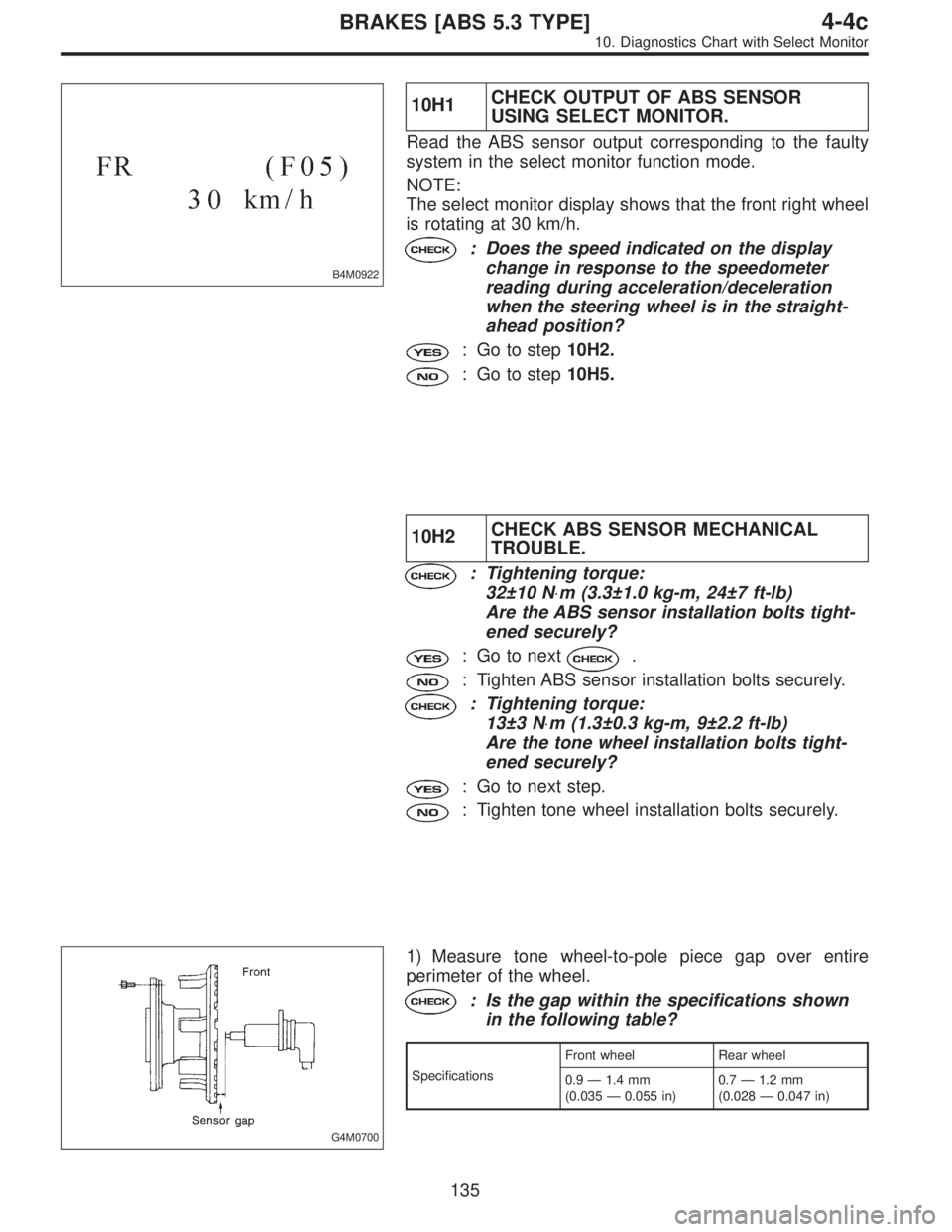
B4M0922
10H1CHECK OUTPUT OF ABS SENSOR
USING SELECT MONITOR.
Read the ABS sensor output corresponding to the faulty
system in the select monitor function mode.
NOTE:
The select monitor display shows that the front right wheel
is rotating at 30 km/h.
: Does the speed indicated on the display
change in response to the speedometer
reading during acceleration/deceleration
when the steering wheel is in the straight-
ahead position?
: Go to step10H2.
: Go to step10H5.
10H2CHECK ABS SENSOR MECHANICAL
TROUBLE.
: Tightening torque:
32±10 N⋅m (3.3±1.0 kg-m, 24±7 ft-lb)
Are the ABS sensor installation bolts tight-
ened securely?
: Go to next.
: Tighten ABS sensor installation bolts securely.
: Tightening torque:
13±3 N⋅m (1.3±0.3 kg-m, 9±2.2 ft-lb)
Are the tone wheel installation bolts tight-
ened securely?
: Go to next step.
: Tighten tone wheel installation bolts securely.
G4M0700
1) Measure tone wheel-to-pole piece gap over entire
perimeter of the wheel.
: Is the gap within the specifications shown
in the following table?
SpecificationsFront wheel Rear wheel
0.9—1.4 mm
(0.035—0.055 in)0.7—1.2 mm
(0.028—0.047 in)
135
4-4cBRAKES [ABS 5.3 TYPE]
10. Diagnostics Chart with Select Monitor
Page 2744 of 3342
10H9CHECK ABS SENSOR MECHANICAL
TROUBLE.
: Tightening torque:
32±10 N⋅m (3.3±1.0 kg-m, 24±7 ft-lb)
Are the ABS sensor installation bolts tight-
ened securely?
: Go to next.
: Tighten ABS sensor installation bolts securely.
: Tightening torque:
13±3 N⋅m (1.3±0.3 kg-m, 9±2.2 ft-lb)
Are the tone wheel installation bolts tight-
ened securely?
: Go to next step.
: Tighten tone wheel installation bolts securely.
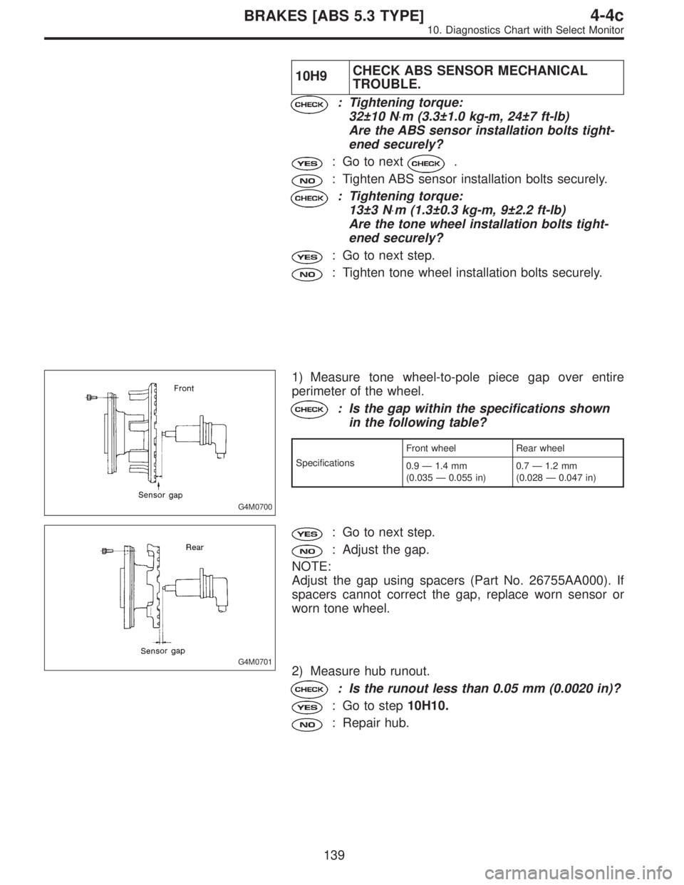
G4M0700
1) Measure tone wheel-to-pole piece gap over entire
perimeter of the wheel.
: Is the gap within the specifications shown
in the following table?
SpecificationsFront wheel Rear wheel
0.9—1.4 mm
(0.035—0.055 in)0.7—1.2 mm
(0.028—0.047 in)
G4M0701
: Go to next step.
: Adjust the gap.
NOTE:
Adjust the gap using spacers (Part No. 26755AA000). If
spacers cannot correct the gap, replace worn sensor or
worn tone wheel.
2) Measure hub runout.
: Is the runout less than 0.05 mm (0.0020 in)?
: Go to step10H10.
: Repair hub.
139
4-4cBRAKES [ABS 5.3 TYPE]
10. Diagnostics Chart with Select Monitor
Page 2751 of 3342
10L6CHECK ABS SENSOR MECHANICAL
TROUBLE.
: Tightening torque:
32±10 N⋅m (3.3±1.0 kg-m, 24±7 ft-lb)
Are the ABS sensor installation bolts tight-
ened securely?
: Go to next.
: Tighten ABS sensor installation bolts securely.
: Tightening torque:
13±3 N⋅m (1.3±0.3 kg-m, 9±2.2 ft-lb)
Are the tone wheel installation bolts tight-
ened securely?
: Go to next step.
: Tighten tone wheel installation bolts securely.
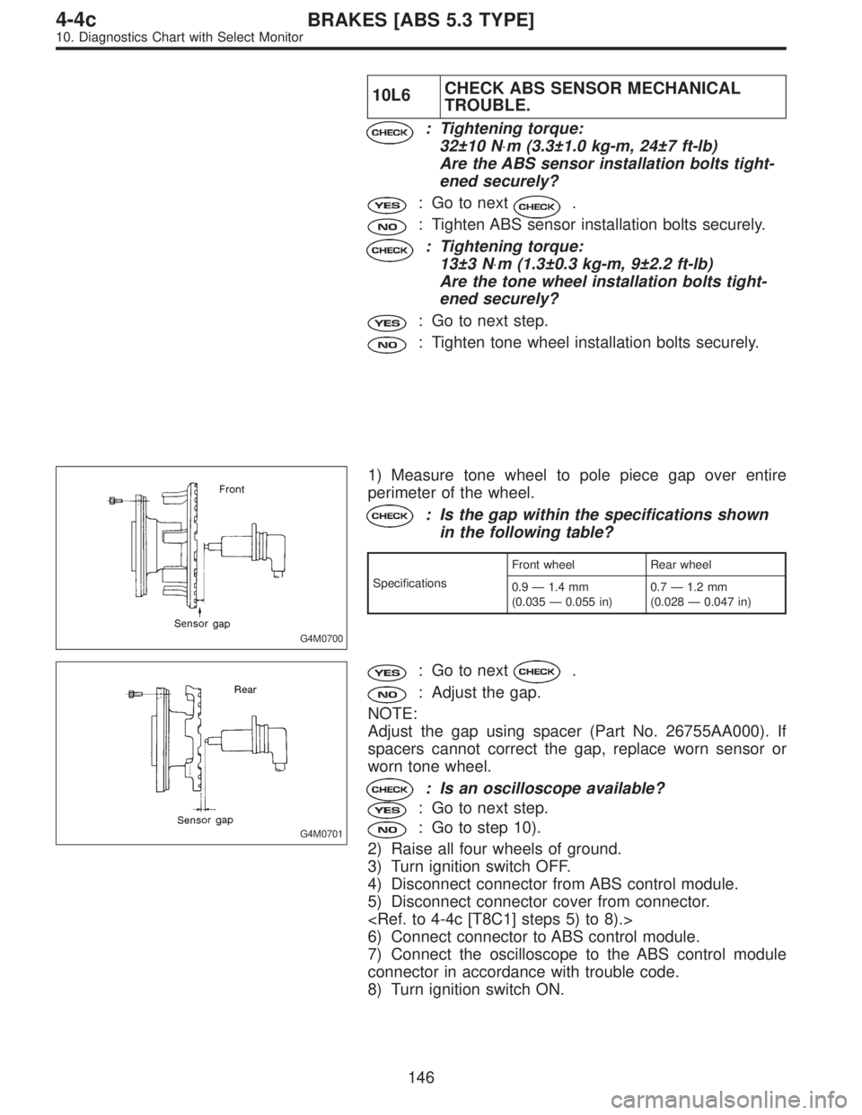
G4M0700
1) Measure tone wheel to pole piece gap over entire
perimeter of the wheel.
: Is the gap within the specifications shown
in the following table?
SpecificationsFront wheel Rear wheel
0.9—1.4 mm
(0.035—0.055 in)0.7—1.2 mm
(0.028—0.047 in)
G4M0701
: Go to next.
: Adjust the gap.
NOTE:
Adjust the gap using spacer (Part No. 26755AA000). If
spacers cannot correct the gap, replace worn sensor or
worn tone wheel.
: Is an oscilloscope available?
: Go to next step.
: Go to step 10).
2) Raise all four wheels of ground.
3) Turn ignition switch OFF.
4) Disconnect connector from ABS control module.
5) Disconnect connector cover from connector.
6) Connect connector to ABS control module.
7) Connect the oscilloscope to the ABS control module
connector in accordance with trouble code.
8) Turn ignition switch ON.
146
4-4cBRAKES [ABS 5.3 TYPE]
10. Diagnostics Chart with Select Monitor
Page 2759 of 3342
10M2
CHECK TIRE.
: Are the tire specifications correct?
: Go to next.
: Replace tire.
: Is the tire worn excessively?
: Replace tire.
: Go to next.
: Is the tire pressure correct?
: Go to step10M3.
: Adjust tire pressure.
10M3CHECK ABS SENSOR MECHANICAL
TROUBLE.
: Tightening torque:
32±10 N⋅m (3.3±1.0 kg-m, 24±7 ft-lb)
Are the ABS sensor installation bolts tight-
ened securely?
: Go to next.
: Tighten ABS sensor installation bolts securely.
: Tightening torque:
13±3 N⋅m (1.3±0.3 kg-m, 9±2.2 ft-lb)
Are the ABS sensor installation bolts tight-
ened securely?
: Go to next step.
: Tighten ABS sensor installation bolts securely.
G4M0700
1) Measure tone wheel to pole piece gap over entire
perimeter of the wheel.
: Is the gap within the specifications shown
in the following table?
SpecificationsFront wheel Rear wheel
0.9—1.4 mm
(0.035—0.055 in)0.7—1.2 mm
(0.028—0.047 in)
154
4-4cBRAKES [ABS 5.3 TYPE]
10. Diagnostics Chart with Select Monitor
Page 2844 of 3342
![SUBARU LEGACY 1997 Service Repair Manual B4M0903A
10AE8CHECK BATTERY SHORT AT ABSCM
MONITOR TERMINAL.
1) Disconnect connector cover from ABSCM connector.
<Ref. to 4-4c [T8C1] steps 5) to 8).>
2) Connect all connectors.
3) Turn ignition switc SUBARU LEGACY 1997 Service Repair Manual B4M0903A
10AE8CHECK BATTERY SHORT AT ABSCM
MONITOR TERMINAL.
1) Disconnect connector cover from ABSCM connector.
<Ref. to 4-4c [T8C1] steps 5) to 8).>
2) Connect all connectors.
3) Turn ignition switc](/manual-img/17/57434/w960_57434-2843.png)
B4M0903A
10AE8CHECK BATTERY SHORT AT ABSCM
MONITOR TERMINAL.
1) Disconnect connector cover from ABSCM connector.
2) Connect all connectors.
3) Turn ignition switch to ON.
4) Measure voltage between ABSCM connector terminals.
: Connector & terminal
(F49) No. 10 (+)—No.1(�)
Is voltage less than 2 V?
: Go to next step.
: Replace ABSCM.
5) Turn ignition switch to OFF.
6) Measure voltage between ABSCM connector terminals.
: Connector & terminals
(F49) No. 10 (+)—No.1(�)
Is voltage less than 2 V?
: Go to step10AE9.
: Replace ABSCM.
B4M0808
10AE9
CHECK MOTOR GROUND.
: Tightening torque:
32±10 N⋅m (3.3±1.0 kg-m, 24±7 ft-lb)
Is the motor ground terminal tightly
clamped?
: Go to step10AE10.
: Tighten the clamp of motor ground terminal.
B4M0904A
10AE10CHECK ABSCM MOTOR DRIVE TERMI-
NAL.
1) Measure voltage between ABSCM connector terminals.
2) Operate the check sequence.
: Connector & terminals
(F49) No. 22 (+)—No.1(�)
Does the voltage drop from 10—13Vto
less than 1.5 V, and rise to 10—13 V again
when carrying out the check sequence?
: Go to step10AE11.
: Replace ABSCM.
239
4-4cBRAKES [ABS 5.3 TYPE]
10. Diagnostics Chart with Select Monitor
Page 2849 of 3342
B4M0808
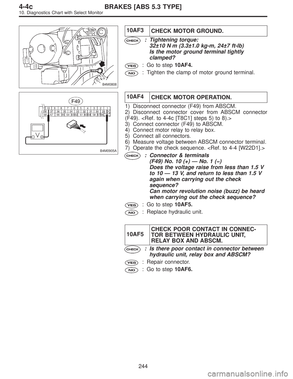
10AF3
CHECK MOTOR GROUND.
: Tightening torque:
32±10 N⋅m (3.3±1.0 kg-m, 24±7 ft-lb)
Is the motor ground terminal tightly
clamped?
: Go to step10AF4.
: Tighten the clamp of motor ground terminal.
B4M0905A
10AF4
CHECK MOTOR OPERATION.
1) Disconnect connector (F49) from ABSCM.
2) Disconnect connector cover from ABSCM connector
(F49).
3) Connect connector (F49) to ABSCM.
4) Connect motor relay to relay box.
5) Connect all connectors.
6) Measure voltage between ABSCM connector terminal.
7) Operate the check sequence.
: Connector & terminals
(F49) No. 10 (+)—No.1(�)
Does the voltage raise from less than 1.5 V
to 10—13 V, and return to less than 1.5 V
again when carrying out the check
sequence?
Can motor revolution noise (buzz) be heard
when carrying out the check sequence?
: Go to step10AF5.
: Replace hydraulic unit.
10AF5CHECK POOR CONTACT IN CONNEC-
TOR BETWEEN HYDRAULIC UNIT,
RELAY BOX AND ABSCM.
: Is there poor contact in connector between
hydraulic unit, relay box and ABSCM?
: Repair connector.
: Go to step10AF6.
244
4-4cBRAKES [ABS 5.3 TYPE]
10. Diagnostics Chart with Select Monitor
Page 2907 of 3342
B4M1240A
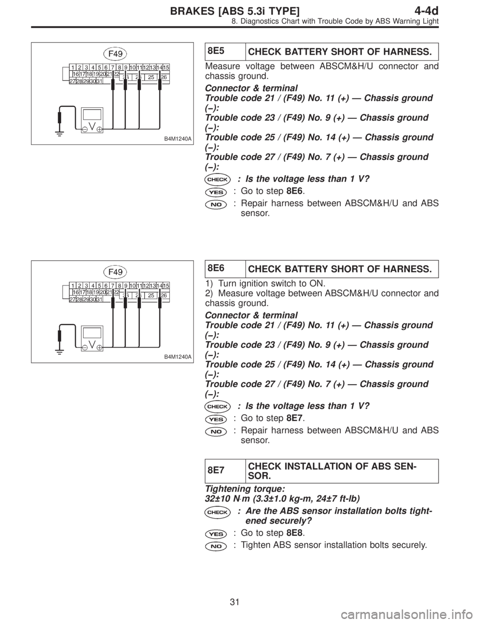
8E5
CHECK BATTERY SHORT OF HARNESS.
Measure voltage between ABSCM&H/U connector and
chassis ground.
Connector & terminal
Trouble code 21 / (F49) No. 11 (+)—Chassis ground
(�):
Trouble code 23 / (F49) No. 9 (+)—Chassis ground
(�):
Trouble code 25 / (F49) No. 14 (+)—Chassis ground
(�):
Trouble code 27 / (F49) No. 7 (+)—Chassis ground
(�):
: Is the voltage less than 1 V?
: Go to step8E6.
: Repair harness between ABSCM&H/U and ABS
sensor.
B4M1240A
8E6
CHECK BATTERY SHORT OF HARNESS.
1) Turn ignition switch to ON.
2) Measure voltage between ABSCM&H/U connector and
chassis ground.
Connector & terminal
Trouble code 21 / (F49) No. 11 (+)—Chassis ground
(�):
Trouble code 23 / (F49) No. 9 (+)—Chassis ground
(�):
Trouble code 25 / (F49) No. 14 (+)—Chassis ground
(�):
Trouble code 27 / (F49) No. 7 (+)—Chassis ground
(�):
: Is the voltage less than 1 V?
: Go to step8E7.
: Repair harness between ABSCM&H/U and ABS
sensor.
8E7CHECK INSTALLATION OF ABS SEN-
SOR.
Tightening torque:
32±10 N⋅m (3.3±1.0 kg-m, 24±7 ft-lb)
: Are the ABS sensor installation bolts tight-
ened securely?
: Go to step8E8.
: Tighten ABS sensor installation bolts securely.
31
4-4dBRAKES [ABS 5.3i TYPE]
8. Diagnostics Chart with Trouble Code by ABS Warning Light