Page 2443 of 3342
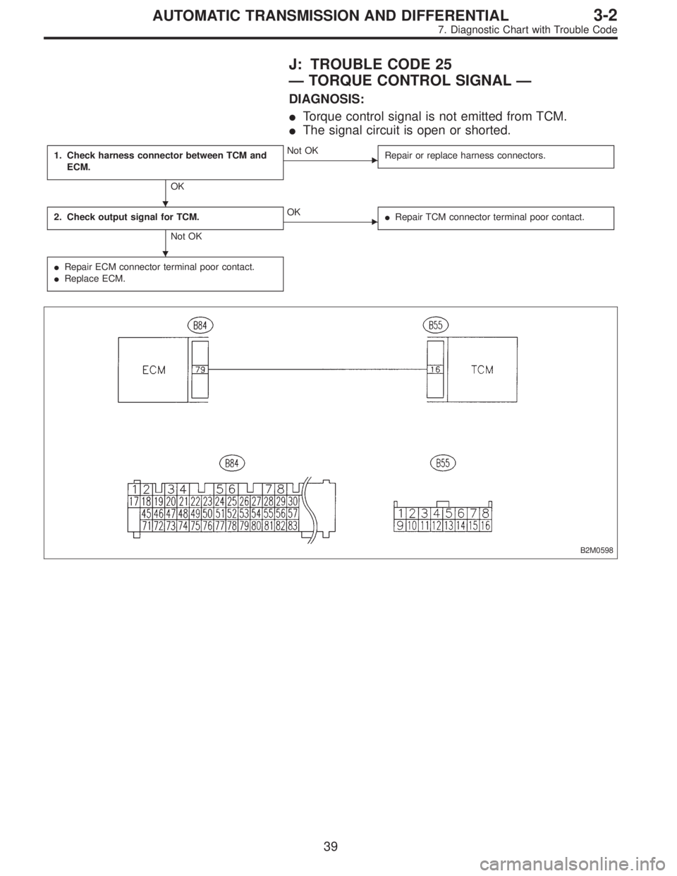
J: TROUBLE CODE 25
—TORQUE CONTROL SIGNAL—
DIAGNOSIS:
�Torque control signal is not emitted from TCM.
�The signal circuit is open or shorted.
1. Check harness connector between TCM and
ECM.
OK
�Not OK
Repair or replace harness connectors.
2. Check output signal for TCM.
Not OK
�OK
�Repair TCM connector terminal poor contact.
�Repair ECM connector terminal poor contact.
�Replace ECM.
B2M0598
�
�
39
3-2AUTOMATIC TRANSMISSION AND DIFFERENTIAL
7. Diagnostic Chart with Trouble Code
Page 2473 of 3342

One-way clutch (3-")
Overrunning clutch
Drive pinion
Crown gear
Axle shaft
Differential gear
Final gear
Seal pipe
Oil pump
High clutch
Band brake
Low & reverse clutch
Reverse clutch
One-way clutch (1-2)
One-way clutch (3-4)
Double oil seal
Input shaft
Output shaft
Planetary gear
Reduction gear
Drive plate
Torque converter one-way clutch
Lock-up facing
Lock-up damper
ATF deterioration
ATF level too high or too low
Differential gear oil level too high or too low
Engine performance
Engine speed signal
Parking brake mechanism
Problem parts
30 31 32 33 34 35 36 37 38 39 40 41 42 43 44 45 46 47 48 49 50 51 52 53 54 55 56 57 58 Symptom
Starter does not rotate when select lever is
in“P”or“N.”; starter rotates when select
lever is“R”,“D”,“3”or“2.”
XXXAbnormal noise when select lever is in“P”or
“N.”
X Hissing noise occurs during standing starts.
X X X X Noise occurs while driving in“D
1”range.
X X X X Noise occurs while driving in“D
2”range.
X X X Noise occurs while driving in“D
3”range.
X X X X Noise occurs while driving in“D
4”range.
XXEngine stalls while shifting from one range to
another.
Vehicle moves when select lever is in“N.”
XShock occurs when select lever is moved
from“N”to“D.”
Excessive time lag occurs when select lever
is moved from“N”to“D.”
XShock occurs when select lever is moved
from“N”to“R.”
XXExcessive time lag occurs when select lever
is moved from“N”to“R.”
XXXX X XXX X XVehicle does not start in any shift range
(engine revving up).
XVehicle does not start in any shift range
(engine stall).
XXVehicle does not start in“R”range only
(engine revving up).
XXVehicle does not start in“R”range only
(engine stall).
XVehicle does not start in“D”or“3”range
(engine revving up).
Vehicle does not start in“D”,“3”or“2”range
(engine revving up).
XVehicle does not start in“D”,“3”or“2”range
(engine stall).
Vehicle starts in“R”range only (engine rev-
ving up).
XXAcceleration during standing starts is poor
(high stall rpm).
XXXAcceleration during standing starts is poor
(low stall rpm).
XX XAcceleration is poor when select lever is in
“D”,“3”or“2”range (normal stall rpm).
XXXXAcceleration is poor when select lever is in
“R”(normal stall rpm).
XNo shift occurs from 1st to 2nd gear.
X X No shift occurs from 2nd to 3rd gear.
XNo shift occurs from 3rd to 4th gear.
No“kick-down”shifts occur.
Engine brake is not effected when select
lever is in“3”range.
30 31 32 33 34 35 36 37 38 39 40 41 42 43 44 45 46 47 48 49 50 51 52 53 54 55 56 57 58
69
3-2AUTOMATIC TRANSMISSION AND DIFFERENTIAL
9. General Diagnostic Table
Page 2475 of 3342

One-way clutch (3-")
Overrunning clutch
Drive pinion
Crown gear
Axle shaft
Differential gear
Final gear
Seal pipe
Oil pump
High clutch
Band brake
Low & reverse clutch
Reverse clutch
One-way clutch (1-2)
One-way clutch (3-4)
Double oil seal
Input shaft
Output shaft
Planetary gear
Reduction gear
Drive plate
Torque converter one-way clutch
Lock-up facing
Lock-up damper
ATF deterioration
ATF level too high or too low
Differential gear oil level too high or too low
Engine performance
Engine speed signal
Parking brake mechanism
Problem parts
30 31 32 33 34 35 36 37 38 39 40 41 42 43 44 45 46 47 48 49 50 51 52 53 54 55 56 57 58 Symptom
XEngine brake is not effected when select
lever is in“3”or“2”range.
XEngine brake is not effected when select
lever is in“1”range.
Shift characteristics are erroneous.
X X No lock-up occurs.
Vehicle cannot be set in“D”range power
mode.
“D”range power mode cannot be released.
X Parking brake is not effected.
XShift lever cannot be moved or is hard to
move from“P”range.
Select lever is hard to move.
Select lever is too light to move (unreason-
able resistance).
X ATF spurts out.
X Differential oil spurts out.
X X Differential oil level changes excessively.
X XXXX X XOdor is produced from oil supply pipe.
XXXShock occurs when select lever is moved
from“1”to“2”range.
XSlippage occurs when select lever is moved
from“1”to“2”range.
XX X XShock occurs when select lever is moved
from“2”to“3”range.
XXSlippage occurs when select lever is moved
from“2”to“3”range.
XX XXShock occurs when select lever is moved
from“3”to“4”range.
XSlippage occurs when select lever is moved
from“3”to“4”range.
XX XShock occurs when select lever is moved
from“3”to“2”range.
XShock occurs when select lever is moved
from“D”to“1”range.
XXShock occurs when select lever is moved
from“2”to“1”range.
XXShock occurs when accelerator pedal is
released at medium speeds.
XXVibration occurs during straight-forward
operation.
Select lever slips out of position during
acceleration or while driving on rough terrain.
XVibration occurs during turns (tight corner
“braking”phenomenon).
Front wheel slippage occurs during standing
starts.
Vehicle is not set in FWD mode.
30 31 32 33 34 35 36 37 38 39 40 41 42 43 44 45 46 47 48 49 50 51 52 53 54 55 56 57 58
71
3-2AUTOMATIC TRANSMISSION AND DIFFERENTIAL
9. General Diagnostic Table
Page 2484 of 3342
P6 14—GNDLess than 0.7 V whe")
Contents Connector No. Terminal No.Input/Output signals
Measured value and measuring conditions
TCS
control
unit ECM
commun-
icationTCS,ECM communication
(torque command)P6 14—GNDLess than 0.7 V when the vehicle stands
still.
TCS,ECM communication
(torque command)P6 5—GNDLess than 5 V when the vehicle stands
still.
TCS,ECM communication
(TCS operates)P6 12—GND4—5.4 V when TCS controls no
operations. Less than 0.7 V when it
controls operations.
ECM,TCS communication
(engine control)P6 4—GNDH/L toggle signal with the accelerator
pedal off (Cycle 20 mS, H: 10—14 V, L:
less than 0.7 V). Less than 2.0 V with the
accelerator pedal depressed. Also when
TCS OFF indicator light comes on by TCS
OFF switch.
ABS operation signal P6 13—GND10—14 V when the ABS control does not
operate still and less than 0.7 V when
ABS operates.
Fluid level sensor P7 20—GNDLess than2VwhenIGNisONand10—
14 V when idling.
Select
monitorData is received. P7 9—GND 4—4.5 V when no data is received.
Data is sent. P7 19—GND 4—4.5 V when no data is sent.
Diagnosis connector P7 8—GND 10—14 V when IGN is ON.
Power
supplyIgnition P5 1—GND 10—14 V when IGN is ON.
Battery P5 4—GND 10—14 V
Grounding
linePower P5 5—body 1Ωor less
Digital P7 15—body 1Ωor less
Power P4 6—body 1Ωor less
8
4-4bBRAKES
5. Control Module I/O Signal
Page 2518 of 3342
 Dismount brake as outlined in manual to gain access to
ABS sensor and tone wheel for inspection.
2) Check pole piece and tone wheel for accum")
G4M0700
G4M0701
1. CHECK ABS SENSOR MECHANICAL TROUBLE.
1) Dismount brake as outlined in manual to gain access to
ABS sensor and tone wheel for inspection.
2) Check pole piece and tone wheel for accumulation of
foreign particles. If necessary, remove foreign particles and
clean.
3) Check tone wheel teeth for cracks for deformities. If
necessary, replace tone wheel (No. of teeth: 44) with a new
one.
4) Check tone wheel for looseness.
Tightening torque:
10—16 N⋅m(1—1.6 kg-m, 7—12 ft-lb)
5) Measure tone wheel-to-pole piece gap over entire
perimeter of the wheel.
SpecificationsFront wheel Rear wheel
0.9—1.4 mm
(0.035—0.055 in)0.7—1.2 mm
(0.028—0.047 in)
If measurements check out“Not OK”, adjust the gap using
spacers (Part No. 26755AA000). If spacers cannot correct
the gap, replace worn sensor or worn tone wheel.
6) Check hub runout.
Specifications 0.05 mm (0.0020 in)
7) The following checks can be made if an oscilloscope is
available.
(1) Raise all four wheels of ground.
(2) Turn ignition switch OFF.
(3) Connect all connectors to ABS control module.
(4) Connect the oscilloscope to the ABS control mod-
ule connector in accordance with trouble code.
(5) Turn ignition switch ON.
42
4-4bBRAKES
8. Diagnostics Chart with Trouble Code
Page 2637 of 3342

Are the ABS sensor installation bolts tight-
ened securely?
: Go to next.
: Tighten ABS sensor in")
8B5CHECK ABS SENSOR MECHANICAL
TROUBLE.
: Tightening torque:
32±10 N⋅m (3.3±1.0 kg-m, 24±7 ft-lb)
Are the ABS sensor installation bolts tight-
ened securely?
: Go to next.
: Tighten ABS sensor installation bolts securely.
: Tightening torque:
13±3 N⋅m (1.3±0.3 kg-m, 9±2.2 ft-lb)
Are the tone wheel installation bolts tight-
ened securely?
: Go to next step.
: Tighten tone wheel installation bolts securely.
G4M0700
1) Measure tone wheel-to-pole piece gap over entire
perimeter of the wheel.
: Is the gap within the specifications shown
in the following table?
SpecificationsFront wheel Rear wheel
0.9—1.4 mm
(0.035—0.055 in)0.7—1.2 mm
(0.028—0.047 in)
G4M0701
: Go to next step.
: Adjust the gap.
NOTE:
Adjust the gap using spacers (Part No. 26755AA000). If
spacers cannot correct the gap, replace worn sensor or
worn tone wheel.
2) Measure hub runout.
: Is the runout less than 0.05 mm (0.0020 in)?
: Go to step8B6.
: Repair hub.
32
4-4cBRAKES [ABS 5.3 TYPE]
8. Diagnostics Chart with Trouble Code
Page 2640 of 3342
WIRING DIAGRAM:
B4M1035
8C1CHECK ABS SENSOR MECHANICAL
TROUBLE.
: Tightening torque:
32±10 N⋅m (3.3±1.0 kg-m, 24±7 ft-lb)
Are the ABS sensor installation bolts tight-
ened securely?
: Go to next.
: Tighten ABS sensor installation bolts securely.
: Tightening torque:
13±3 N⋅m (1.3±0.3 kg-m, 9±2.2 ft-lb)
Are the tone wheel installation bolts tight-
ened securely?
: Go to next step.
: Tighten tone wheel installation bolts securely.
35
4-4cBRAKES [ABS 5.3 TYPE]
8. Diagnostics Chart with Trouble Code
Page 2649 of 3342
8D2
CHECK TIRE.
: Are the tire specifications correct?
: Go to next.
: Replace tire.
: Is the tire worn excessively?
: Replace tire.
: Go to next.
: Is the tire pressure correct?
: Go to step8D3.
: Adjust tire pressure.
8D3CHECK ABS SENSOR MECHANICAL
TROUBLE.
: Tightening torque:
32±10 N⋅m (3.3±1.0 kg-m, 24±7 ft-lb)
Are the ABS sensor installation bolts tight-
ened securely?
: Go to next.
: Tighten ABS sensor installation bolts securely.
: Tightening torque:
13±3 N⋅m (1.3±0.3 kg-m, 9±2.2 ft-lb)
Are the tone wheel installation bolts tight-
ened securely?
: Go to next step.
: Tighten tone wheel installation bolts securely.
G4M0700
1) Measure tone wheel to pole piece gap over entire
perimeter of the wheel.
: Is the gap within the specifications shown
in the following table?
SpecificationsFront wheel Rear wheel
0.9—1.4 mm
(0.035—0.055 in)0.7—1.2 mm
(0.028—0.047 in)
44
4-4cBRAKES [ABS 5.3 TYPE]
8. Diagnostics Chart with Trouble Code

Are the ABS sensor installation bolts tight-
ened securely?
: Go to next.")
