Page 1740 of 3342

1. Precaution
�Before disassembling or reassembling parts, always
disconnect battery ground cable. When repairing
radio, control modules, etc. which are provided with
memory functions, record memory contents before
disconnecting battery ground cable. Otherwise, these
contents are cancelled upon disconnection.
�Reassemble parts in reverse order of disassembly
procedure unless otherwise indicated.
�Adjust parts to specifications contained in this
manual if so designated.
�Connect connectors and hoses securely during
reassembly.
�After reassembly, ensure functional parts operate
smoothly.
CAUTION:
�Airbag system wiring harness is routed near the
electrical parts and switch.
�All Airbag system wiring harness and connectors
are colored yellow. Do not use electrical test equip-
ment on these circuit.
�Be careful not to damage Airbag system wiring har-
ness when servicing the ignition key cylinder.
G6M0102
2. Battery
A: REMOVAL AND INSTALLATION
1. BATTERY
1) Disconnect the positive (+) terminal after disconnecting
the negative (�) terminal of battery.
2) Remove flange nuts from battery rods and take off bat-
tery holder.
3) Remove battery.
Tightening torque:
3.4±1.0 N⋅m (0.35±0.1 kg-m, 2.5±0.7 ft-lb)
NOTE:
�Clean battery cable terminals and apply grease to retard
the formation of corrosion.
�Connect the positive (+) terminal of battery and then the
negative (�) terminal of the battery.
4
6-2SERVICE PROCEDURE
1. Precaution - 2. Battery
Page 1748 of 3342
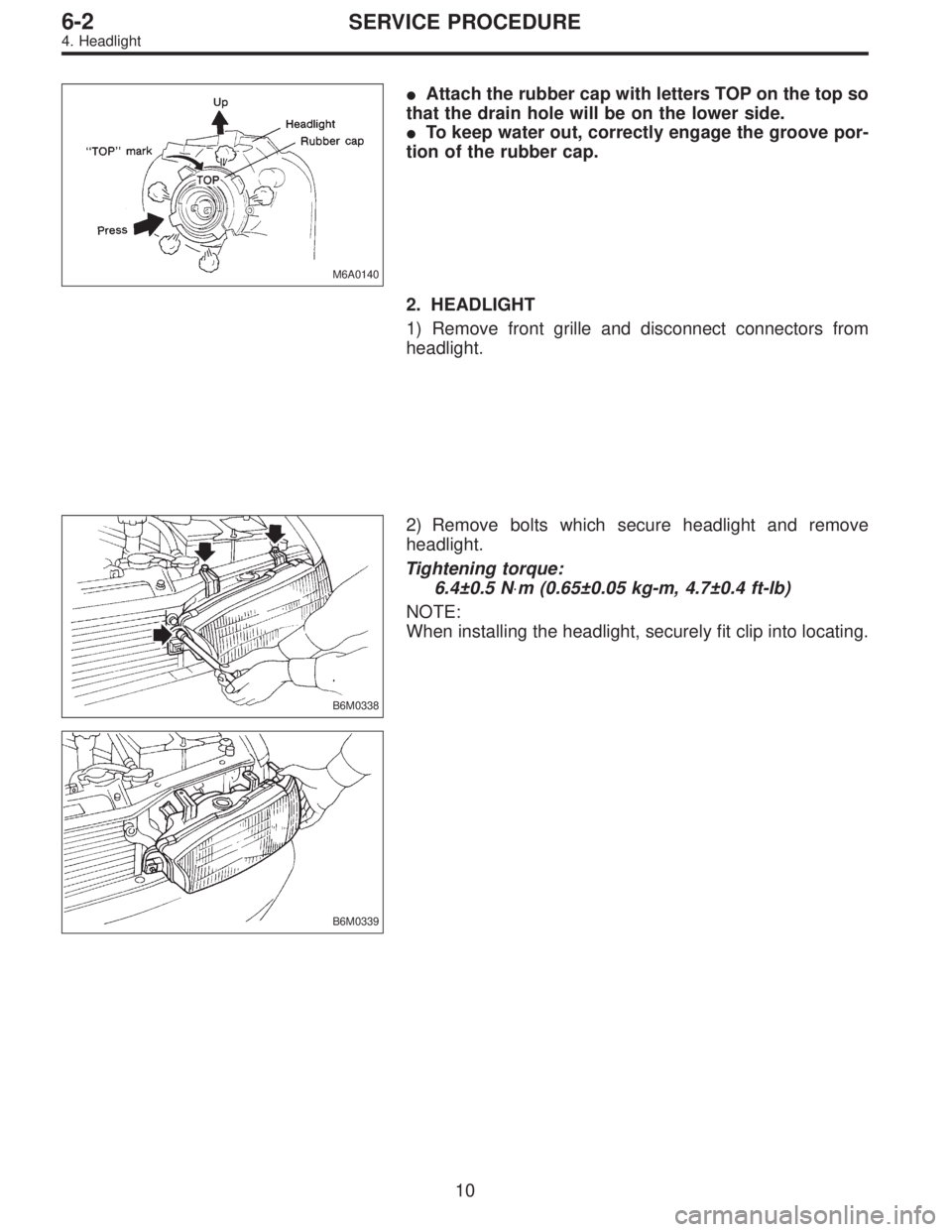
M6A0140
�Attach the rubber cap with letters TOP on the top so
that the drain hole will be on the lower side.
�To keep water out, correctly engage the groove por-
tion of the rubber cap.
2. HEADLIGHT
1) Remove front grille and disconnect connectors from
headlight.
B6M0338
2) Remove bolts which secure headlight and remove
headlight.
Tightening torque:
6.4±0.5 N⋅m (0.65±0.05 kg-m, 4.7±0.4 ft-lb)
NOTE:
When installing the headlight, securely fit clip into locating.
B6M0339
10
6-2SERVICE PROCEDURE
4. Headlight
Page 1753 of 3342
 Remove rear trim.
2) Disconnect connector from rear combination light.
3) Remove nuts which secure rea")
B6M0055A
B6M0056A
5. Stop and Tail Light
A: REMOVAL AND INSTALLATION
1. REAR COMBINATION LIGHT
1) Remove rear trim.
2) Disconnect connector from rear combination light.
3) Remove nuts which secure rear combination light.
Tightening torque:
2.5±0.5 N⋅m (0.25±0.05 kg-m, 1.8±0.4 ft-lb)
4) Attach adhesive cloth tape to body area around rear
combination light.
5) Using a standard screwdriver, carefully pry rear combi-
nation light off and away from the vehicle.
CAUTION:
�Do not pry rear combination light forcefully as this
may scratch vehicle body.
�Remove all traces of adhesive tape from body before
installation.
�Attach butyl rubber tape to back of rear combination
light before installing rear combination light on body
for sealing purposes.
B6M0057A
B6M0058A
2. REAR FINISHER
1) Remove trunk lid trim (SEDAN) or rear gate trim
(WAGON).
2) Disconnect connectors from rear finisher.
3) Remove rear wiper motor (WAGON).
4) Remove nuts which secure rear finisher.
Tightening torque:
2.5±0.5 N⋅m (0.25±0.05 kg-m, 1.8±0.4 ft-lb)
5) Attach adhesive cloth tape to body area around rear
finisher.
6) Using a standard screwdriver, carefully pry rear finisher
off and away from the vehicle.
CAUTION:
Do not pry rear finisher forcefully as this may scratch
vehicle body.
15
6-2SERVICE PROCEDURE
5. Stop and Tail Light
Page 1764 of 3342
 Open engine hood.
2) Remove cap of wiper arm installation nut.
3) Remove the nut which secures wiper arm.
4) Remove wiper arm.
5) Installation is in the reverse order of remova")
G6M0118
2. WIPER ARM
1) Open engine hood.
2) Remove cap of wiper arm installation nut.
3) Remove the nut which secures wiper arm.
4) Remove wiper arm.
5) Installation is in the reverse order of removal.
NOTE:
Remove metal sludge from the wiper arm fixture before
installing it.
Tightening torque:
20±3 N⋅m (2.0±0.3 kg-m, 14.5±2.2 ft-lb)
3. WIPER MOTOR AND LINK
1) Detach weatherstrip and cowl panel.
[W10A0].>
NOTE:
Apply silicone oil or soap water to both sides of cowl net to
facilitate removal.
B6M0108
2) Disconnect connector of wiper motor.
3) Remove motor attaching bolts.
Tightening torque:
5.9±1.5 N⋅m (0.6±0.15 kg-m, 4.3±1.1 ft-lb)
4) Remove wiper link from back side of wiper motor using
a screwdriver inserted into service hole in front panel.
CAUTION:
Do not pry wiper link off forcefully as this may scratch
vehicle body.
5) Remove wiper motor.
6) Separate the driver’s side wiper link from back side of
the passenger’s side wiper sleeve unit.
24
6-2SERVICE PROCEDURE
10. Front Wiper and Washer
Page 1765 of 3342
G6M0021
7) Remove nuts which secure sleeve unit.
Tightening torque:
5.9±1.5 N⋅m (0.6±0.15 kg-m, 4.3±1.1 ft-lb)
G6M0121
8) Remove wiper link from service hole in front panel.
B6M0109A
4. WASHER TANK AND WASHER MOTOR
1) Remove washer tank attaching bolts.
2) Disconnect connectors of washer motors.
3) Disconnect washer hoses from each washer motor.
4) Remove washer tank and washer motor as an unit.
5) Separate washer motor from washer tank.
B6M0110A
5. NOZZLE
1) Disconnect washer hose from nozzle.
2) Push nozzle clip in direction A as shown in figure.
3) Remove nozzle from engine hood.
CAUTION:
Do not pry nozzle off forcefully as this may scratch
vehicle body.
6. COMBINATION SWITCH
Refer to 6-2 [W4B3] as for removal and installation of com-
bination switch.
25
6-2SERVICE PROCEDURE
10. Front Wiper and Washer
Page 1768 of 3342
G6M0126
11. Rear Wiper and Washer
A: ON-CAR SERVICES
1. ADJUSTMENT
1) Adjust wiper blade in original position as shown in fig-
ure by changing wiper arm installation.
Original position:
A: 25 — 35 mm (0.98 — 1.38 in)
G6M0127
2) Adjust washer ejecting point on rear gate window as
shown in figure when the vehicle stops.
Ejecting point:
A: 25 mm (0.98 in)
B: 200 — 300 mm (7.87 — 11.81 in)
B6M0107A
B: REMOVAL AND INSTALLATION
1. BLADE
Pull out blade following the arrow direction, from arm while
pushing up locking clip.
B6M0112
2. WIPER ARM
1) Remove head cover.
2) Remove nut and wiper arm.
Tightening torque:
5.9±1.5 N⋅m (0.6±0.15 kg-m, 4.3±1.1 ft-lb)
B6M0113
3. WIPER MOTOR
1) Remove cap and special nut.
CAUTION:
Be careful not to strike service tool against nozzle dur-
ing removal.
Tightening torque:
7.4±1.5 N⋅m (0.75±0.15 kg-m, 5.4±1.1 ft-lb)
28
6-2SERVICE PROCEDURE
11. Rear Wiper and Washer
Page 1769 of 3342
2) Remove rear gate trim.
3) Undo clips which secure harness, and disconnect con-
nector of wiper motor.
B6M0114
4) Separate washer hoses at joint.
5) Remove attaching screws and take out wiper motor
assembly.
CAUTION:
Be careful not to damage O-ring when removing wiper
motor assembly.
Tightening torque:
5.9±1.5 N⋅m (0.6±0.15 kg-m, 4.3±1.1 ft-lb)
4. WASHER TANK AND WASHER MOTOR
Refer to 6-2 [W10B4] as for removal and installation of
washer tank and washer motor.
5. COMBINATION SWITCH
Refer to 6-2 [W4B3] as for removal and installation of com-
bination switch.
C: DISASSEMBLY AND ASSEMBLY
1. COMBINATION SWITCH
Refer to 6-2 [W4C1] as for disassembly and assembly of
combination switch.
29
6-2SERVICE PROCEDURE
11. Rear Wiper and Washer
Page 1778 of 3342
C: INSTALLATION
CAUTION:
�Ensure sensor mounting hole is clean and free of
foreign matter.
�Apply grease to tip end of key to prevent key from
falling off sensor.
�Align tip end of key with key groove on end of
speedometer shaft during installation.
1) Hand tighten vehicle speed sensor 2, then tighten it
using suitable tool.
Tightening torque required for sensor to reach bottom of
transmission is as follows:
Tightening torque:
0.39—0.88 N⋅m (4.0—9.0 kg-cm, 3.5—7.8 in-lb)
CAUTION:
�When torque must be applied that exceeds 0.88 N⋅m
(9.0 kg-cm, 7.8 in-lb), the key and key groove on end of
speedometer may not be aligned properly. Remove the
key, align it correctly and reassemble.
�Sensor threads are secured by Locktite. The reas-
sembly must be completed within 5 minutes before
Locktite dries.
2) Tighten vehicle speed sensor 2 further to specified
torque.
Tightening torque:
5.9±1.5 N⋅m (60±15 kg-cm, 52±13 in-lb)
36
6-2SERVICE PROCEDURE
14. Vehicle Speed Sensor 2
 Remove nuts which secure sleeve unit.
Tightening torque:
5.9±1.5 N⋅m (0.6±0.15 kg-m, 4.3±1.1 ft-lb)
G6M0121
8) Remove wiper link from service hole in front panel.
B6M0109A
4. WASHER TA")
 Adjust wiper blade in original position as shown in fig-
ure by changing wiper arm installation.
Original position:
A: 25 — 35 m")
![SUBARU LEGACY 1997 Service Repair Manual 2) Remove rear gate trim. <Ref. to 5-2 [W3A1].>
3) Undo clips which secure harness, and disconnect con-
nector of wiper motor.
B6M0114
4) Separate washer hoses at joint.
5) Remove attaching screws and](/manual-img/17/57434/w960_57434-1768.png "SUBARU LEGACY 1997 Service Repair Manual 2) Remove rear gate trim. <Ref. to 5-2 [W3A1].>
3) Undo clips which secure harness, and disconnect con-
nector of wiper motor.
B6M0114
4) Separate washer hoses at joint.
5) Remove attaching screws and")
