Page 1653 of 3342
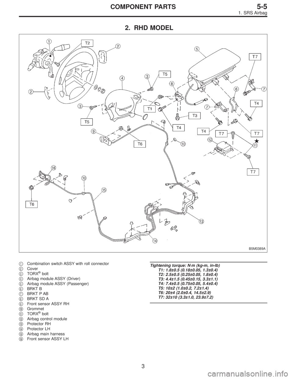
2. RHD MODEL
B5M0389A
�1Combination switch ASSY with roll connector
�
2Cover
�
3TORX®bolt
�
4Airbag module ASSY (Driver)
�
5Airbag module ASSY (Passenger)
�
6BRKT B
�
7BRKT P AB
�
8BRKT SD A
�
9Front sensor ASSY RH
�
10Grommet
�
11TORX®bolt
�
12Airbag control module
�
13Protector RH
�
14Protector LH
�
15Airbag main harness
�
16Front sensor ASSY LH
Tightening torque: N⋅m (kg-m, in-lb)
T1: 1.8±0.5 (0.18±0.05, 1.3±0.4)
T2: 2.5±0.5 (0.25±0.05, 1.8±0.4)
T3: 4.4±1.5 (0.45±0.15, 3.3±1.1)
T4: 7.4±0.5 (0.75±0.05, 5.4±0.4)
T5: 10±2 (1.0±0.2, 7.2±1.4)
T6: 20±4 (2.0±0.4, 14.5±2.9)
T7: 32±10 (3.3±1.0, 23.9±7.2)
3
5-5COMPONENT PARTS
1. SRS Airbag
Page 1676 of 3342
1. SRS Airbag
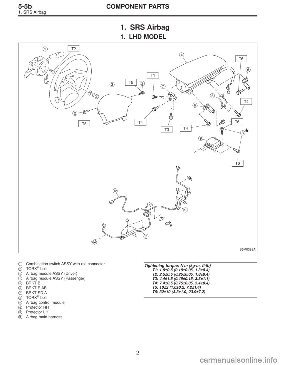
1. LHD MODEL
B5M0399A
�1Combination switch ASSY with roll connector
�
2TORX®bolt
�
3Airbag module ASSY (Driver)
�
4Airbag module ASSY (Passenger)
�
5BRKT B
�
6BRKT P AB
�
7BRKT SD A
�
8TORX®bolt
�
9Airbag control module
�
10Protector RH
�
11Protector LH
�
12Airbag main harness
Tightening torque: N⋅m (kg-m, ft-lb)
T1: 1.8±0.5 (0.18±0.05, 1.3±0.4)
T2: 2.5±0.5 (0.25±0.05, 1.8±0.4)
T3: 4.4±1.5 (0.45±0.15, 3.3±1.1)
T4: 7.4±0.5 (0.75±0.05, 5.4±0.4)
T5: 10±2 (1.0±0.2, 7.2±1.4)
T6: 32±10 (3.3±1.0, 23.9±7.2)
2
5-5bCOMPONENT PARTS
1. SRS Airbag
Page 1677 of 3342
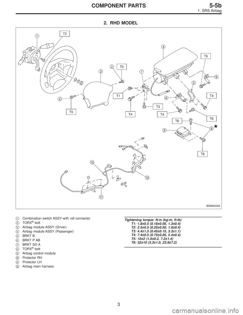
2. RHD MODEL
B5M0434A
�1Combination switch ASSY with roll connector
�
2TORX®bolt
�
3Airbag module ASSY (Driver)
�
4Airbag module ASSY (Passenger)
�
5BRKT B
�
6BRKT P AB
�
7BRKT SD A
�
8TORX®bolt
�
9Airbag control module
�
10Protector RH
�
11Protector LH
�
12Airbag main harness
Tightening torque: N⋅m (kg-m, ft-lb)
T1: 1.8±0.5 (0.18±0.05, 1.3±0.4)
T2: 2.5±0.5 (0.25±0.05, 1.8±0.4)
T3: 4.4±1.5 (0.45±0.15, 3.3±1.1)
T4: 7.4±0.5 (0.75±0.05, 5.4±0.4)
T5: 10±2 (1.0±0.2, 7.2±1.4)
T6: 32±10 (3.3±1.0, 23.9±7.2)
3
5-5bCOMPONENT PARTS
1. SRS Airbag
Page 1697 of 3342

1. Engine Electrical
A: SPECIFICATIONS
1. EXCEPT 2200 cc MODEL
Item Designation
StarterType Reduction type
ModelMT
TN128000-8311AT
TN128000-8321
Manufacturer NIPPONDENSO TENNESSEE
Voltage and output 12 V — 1.0 kW 12 V — 1.4 kW
Direction of rotation Counterclockwise (when observed from pinion)
Number of pinion teeth 8 9
No-load
characteristicsVoltage 11 V
Current 90 A or less
Rotating
speed3,000 rpm or more 2,900 rpm or more
Load
characteristicsVoltage 8 V
Current 280 A or less 370 A or less
Torque 9.8 N⋅m (1.0 kg-m, 7.2 ft-lb) 13.7 N⋅m (1.4 kg-m, 10.1 ft-lb)
Rotating
speed900 rpm or more 880 rpm or more
Lock
characteristicsVoltage 5 V
Current 800 A or less 1,050 A or less
Torque 27.5 N⋅m (2.8 kg-m, 20.3 ft-lb) or more
GeneratorType Rotating-field three-phase type, Voltage regulator built-in type
Model LR185-701H
Manufacturer HITACHI AUTOMOTIVE PRODUCTS
Voltage and output 12 V — 85 A
Polarity on ground side Negative
Rotating direction Clockwise (when observed from pulley side)
Armature connection 3-phase Y-type
Output current1,500 rpm — 35 A or more
2,500 rpm — 62 A or more
5,000 rpm — 82 A or more
Regulated voltage 14.5
+0.3
�0.4V [20°C (68°F)]
Ignition
coilModel F-569-01R
Manufacturer Diamond
Primary coil resistance 0.69Ω±10%
Secondary coil resistance 21.0 kΩ±15%
Insulation resistance between
primary terminal and caseMore than 10 MΩ
Spark
plugType and manufacturerRC10YC4 .......... CHAMPION
Alternate
(BKR6E-11 .......... NGK
K20PR-U11 .......... NIPPONDENSO)
Thread size mm 14, P = 1.25
Spark gap mm (in) 1.0 — 1.1 (0.039 — 0.043)
2
6-1SPECIFICATIONS AND SERVICE DATA
1. Engine Electrical
Page 1698 of 3342

2. 2200 cc MODEL
Item Designation
StarterType Reduction type
ModelMT
TN128000-8311AT
TN128000-8321
Manufacturer NIPPONDENSO TENNESSEE
Voltage and output 12 V—1.0 kW 12 V—1.4 kW
Direction of rotation Counterclockwise (when observed from pinion)
Number of pinion teeth 8 9
No-load
characteristicsVoltage 11 V
Current 90 A or less
Rotating
speed3,000 rpm or more 2,900 rpm or more
Load
characteristicsVoltage 8 V
Current 280 A or less 370 A or less
Torque 9.8 N⋅m (1.0 kg-m, 7.2 ft-lb) 13.7 N⋅m (1.4 kg-m, 10.1 ft-lb)
Rotating
speed900 rpm or more 880 rpm or more
Lock
characteristicsVoltage 5 V
Current 800 A or less 1,050 A or less
Torque 27.5 N⋅m (2.8 kg-m, 20.3 ft-lb) or more
GeneratorType Rotating-field three-phase type, Voltage regulator built-in type
Model LR185-701H
Manufacturer HITACHI AUTOMOTIVE PRODUCTS
Voltage and output 12 V—85 A
Polarity on ground side Negative
Rotating direction Clockwise (when observed from pulley side)
Armature connection 3-phase Y-type
Output current1,500 rpm—35 A or more
2,500 rpm—62 A or more
5,000 rpm—82 A or more
Regulated voltage 14.5
+0.3
�0.4V [20°C (68°F)]
Ignition
coilModel FH0047-01R
Manufacturer DEMCO
Primary coil resistance 0.73Ω±10%
Secondary coil resistance 12.8 kΩ±15%
Insulation resistance between
primary terminal and caseMore than 10 MΩ
Spark
plugType and manufacturerRC10YC4 .......... CHAMPION
Alternate
(BKR6E-11 .......... NGK
K20PR-U11 .......... NIPPONDENSO)
Thread size mm 14, P = 1.25
Spark gap mm (in) 1.0—1.1 (0.039—0.043)
3
6-1SPECIFICATIONS AND SERVICE DATA
1. Engine Electrical
Page 1701 of 3342
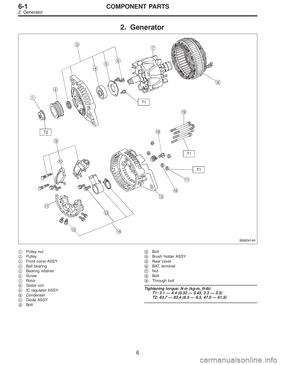
2. Generator
B6M0414A
�1Pulley nut
�
2Pulley
�
3Front cover ASSY
�
4Ball bearing
�
5Bearing retainer
�
6Screw
�
7Rotor
�
8Stator coil
�
9IC regulator ASSY
�
10Condenser
�
11Diode ASSY
�
12Bolt�
13Bolt
�
14Brush holder ASSY
�
15Rear cover
�
16BAT. terminal
�
17Nut
�
18Bolt
�
19Through bolt
Tightening torque: N⋅m (kg-m, ft-lb)
T1: 3.1 — 4.4 (0.32 — 0.45, 2.3 — 3.3)
T2: 63.7 — 83.4 (6.5 — 8.5, 47.0 — 61.5)
6
6-1COMPONENT PARTS
2. Generator
Page 1702 of 3342
G6M0095
1. Starter
A: REMOVAL AND INSTALLATION
1) Disconnect battery ground cable.
G2M0309
2) Disconnect connector and terminal from starter.
3) Remove starter from transmission.
4) Installation is in the reverse order of removal.
Tightening torque:
50±4 N⋅m (5.1±0.4 kg-m, 36.9±2.9 ft-lb)
B: TEST
1. MAGNETIC SWITCH
CAUTION:
�The following magnetic switch tests should be per-
formed with specified voltage applied.
�Each test should be conducted within 3 to 5 sec-
onds. Power to be furnished should be one-half the
rated voltage.
B6M0415A
1) Pull-in test
Connect two battery negative leads onto magnetic switch
body and terminal C respectively. Then connect battery
positive lead onto terminal 50. Pinion should extend when
lead connections are made.
B6M0416A
2) Holding-in test
Disconnect lead from terminal C with pinion extended. Pin-
ion should be held in the extended position.
7
6-1SERVICE PROCEDURE
1. Starter
Page 1703 of 3342
 Return test
Connect two battery negative leads onto terminal 50 and
onto switch body respectively. Then connect battery posi-
tive lead onto terminal C. Next, disconnect lead from ter-
min")
B6M0417A
3) Return test
Connect two battery negative leads onto terminal 50 and
onto switch body respectively. Then connect battery posi-
tive lead onto terminal C. Next, disconnect lead from ter-
minal 50. Pinion should return immediately.
2. PERFORMANCE TEST
The starter is required to produce a large torque and high
rotating speed, but these starter characteristics vary with
the capacity of the battery. It is therefore important to use
a battery with the specified capacity whenever testing the
starter.
The starter should be checked for the following three items:
1. No-load test
Measure the maximum rotating speed and current under a
no-load state.
2. Load test
Measure the magnitude of current needed to generate the
specified torque and rotating speed.
3. Stall test
Measure the torque and current when the armature is
locked.
B6M0418A
1) No-load test
Run single starter under no-load state, and measure its
rotating speed, voltage, and current, using the specified
battery. Measured values must meet the following stan-
dards:
No-load test (Standard):
Voltage/Current
11 V/90 A, or more
Rotating speed
TN128000-8311: 3,000 rpm, or more
TN128000-8321: 3,350 rpm, or more
8
6-1SERVICE PROCEDURE
1. Starter
 Disconnect battery ground cable.
G2M0309
2) Disconnect connector and terminal from starter.
3) Remove starter from transmission.
4) Installation is in")