Page 1589 of 3342
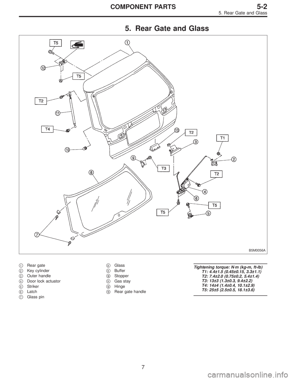
5. Rear Gate and Glass
B5M0056A
�1Rear gate
�
2Key cylinder
�
3Outer handle
�
4Door lock actuator
�
5Striker
�
6Latch
�
7Glass pin�
8Glass
�
9Buffer
�
10Stopper
�
11Gas stay
�
12Hinge
�
13Rear gate handle
Tightening torque: N⋅m (kg-m, ft-lb)
T1: 4.4±1.5 (0.45±0.15, 3.3±1.1)
T2: 7.4±2.0 (0.75±0.2, 5.4±1.4)
T3: 13±3 (1.3±0.3, 9.4±2.2)
T4: 14±4 (1.4±0.4, 10.1±2.9)
T5: 25±5 (2.5±0.5, 18.1±3.6)
7
5-2COMPONENT PARTS
5. Rear Gate and Glass
Page 1590 of 3342
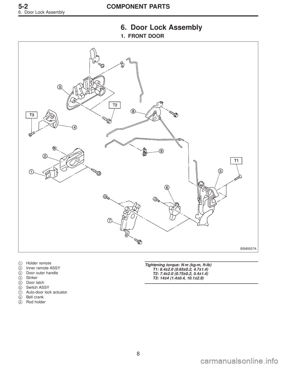
6. Door Lock Assembly
1. FRONT DOOR
B5M0057A
�1Holder remote
�
2Inner remote ASSY
�
3Door outer handle
�
4Striker
�
5Door latch
�
6Switch ASSY
�
7Auto-door lock actuator
�
8Bell crank
�
9Rod holder
Tightening torque: N⋅m (kg-m, ft-lb)
T1: 6.4±2.0 (0.65±0.2, 4.7±1.4)
T2: 7.4±2.0 (0.75±0.2, 5.4±1.4)
T3: 14±4 (1.4±0.4, 10.1±2.9)
8
5-2COMPONENT PARTS
6. Door Lock Assembly
Page 1591 of 3342
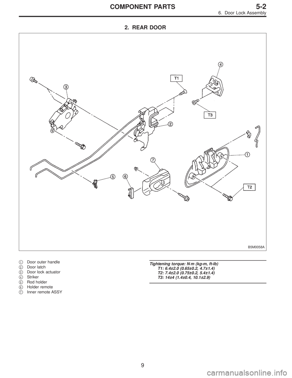
2. REAR DOOR
B5M0058A
�1Door outer handle
�
2Door latch
�
3Door lock actuator
�
4Striker
�
5Rod holder
�
6Holder remote
�
7Inner remote ASSY
Tightening torque: N⋅m (kg-m, ft-lb)
T1: 6.4±2.0 (0.65±0.2, 4.7±1.4)
T2: 7.4±2.0 (0.75±0.2, 5.4±1.4)
T3: 14±4 (1.4±0.4, 10.1±2.9)
9
5-2COMPONENT PARTS
6. Door Lock Assembly
Page 1595 of 3342
G5M0486
2. Door
A: REMOVAL AND INSTALLATION
1. DOOR ASSY
1) Remove lower trim and disconnect connectors from
body harness.
2) Place a cloth or a wood block under door to prevent
damage, and support it with a jack.
3) Remove checker pin by driving it upward. Be careful not
to damage door and body.
G5M0385
4) Remove bolts (M8) securing upper and lower hinges to
door, and remove door from hinges.
Tightening torque:
25±3 N⋅m (2.5±0.3 kg-m, 18.1±2.2 ft-lb)
5) Remove hinges by loosening hinges mounting bolt (M8)
off of body.
Tightening torque:
29±5 N⋅m (3.0±0.5 kg-m, 21.7±3.6 ft-lb)
CAUTION:
Work carefully to avoid damaging door.
6) Installation is in the reverse order of removal.
NOTE:
Apply grease to moving parts of door hinges.
B5M0329A
2. TRIM PANEL
1) Press retainer spring�
1with a thin flat bladed screw-
driver and then remove regulator handle�
2. (models with-
out power window)
B5M0061A
2) Remove gusset cover�1and three screws.
13
5-2SERVICE PROCEDURE
2. Door
Page 1597 of 3342
G5M0392
4. CHECKER
1) Remove trim panel.
2) Remove sealing cover.
3) Apply a cloth to door and body to prevent damaging
them, and remove checker pin by driving it upward.
CAUTION:
Be careful not to damage door and body.
4) Completely close door glass.
5) Loosen two nuts securing checker, and take out
checker through access hole in underside.
Installation should be made in the reverse order of
removal.
Tightening torque:
7.4±2.0 N⋅m (0.75±0.2 kg-m, 5.4±1.4 ft-lb)
5. DOOR GLASS
1) Remove trim panel.
2) Remove sealing cover.
3) Disconnect door mirror connector and then remove
gusset�
1.
4) Remove inner remote.
B5M0063A
5) Remove inner stabilizer�1.
B5M0064A
6) Remove nut and then separate glass holder�1from
guide channel A�
2.
NOTE:
When removing nut, move door window lower glass con-
necting section to service hole of door panel.
7) Remove window glass upward.
CAUTION:
After removing window glass, do not move regulator.
15
5-2SERVICE PROCEDURE
2. Door
Page 1599 of 3342
7. DOOR LATCH
1) Remove trim panel.
2) Remove inner remote assembly.
3) Remove sealing cover around latch service hole.
to 5-2 [W2A3].>
4) Completely close door glass.
B5M0067
5) Remove latch and actuator assembly.
(1) Turn rod holder to disconnect joint between key
lock and rod.
(2) Turn rod holder to disconnect joint between outer
handle and rod.
(3) Turn rod holder to disconnect joint between crank
and rod.
G5M0396
6) Loosen screws securing both latch and actuator, then
remove latch and actuator assembly through service hole
in bottom.
Tightening torque (screw):
6.4±2.0 N⋅m (0.65±0.2 kg-m, 4.7±1.4 ft-lb)
7) Installation is in the reverse order of removal.
Some special items will be described below.
8) Check operation of each part.
9) Check each sliding part for proper lubrication.
CAUTION:
After installation, be sure lock mechanism operates
normally.
17
5-2SERVICE PROCEDURE
2. Door
Page 1600 of 3342
B5M0068
8. OUTER HANDLE
1) Remove trim panel.
2) Remove sealing cover.
3) Detach door latch rod from outer handle and key lock.
4) Loosen nut securing outer handle and then remove
outer handle from outside.
CAUTION:
Be careful not to damage door.
Installation is in the reverse order of removal.
Tightening torque:
7.4±2.0 N⋅m (0.75±0.2 kg-m, 5.4±1.4 ft-lb)
B5M0069A
9. KEY LOCK
1) Remove trim panel.
2) Remove sealing cover.
3) Completely close door glass.
4) Remove outer handle.
5) Loosen spring�
1securing key lock.
6) Remove key lock from outer handle.
Installation is in the reverse order of removal.
NOTE:
Install so that key slot in key lock comes to center of hole
in outer handle.
B5M0070A
10. GUSSET
NOTE:
Be sure window is all the way down.
1) Remove trim panel.
2) Remove door rearview mirror.
3) Remove sealing cover.
4) Remove bolts and nuts which secure gusset.
5) Lift out gusset�
1.
To install, reverse the above removal procedures.
18
5-2SERVICE PROCEDURE
2. Door
Page 1601 of 3342
B5M0467A
11. REAR DOOR CATCHER
1) Open the rear door.
2) Using TORX
®BIT (Tamper resistant type), remove rear
door catcher.
3) Installation is in the reverse order of removal.
Tightening torque:
37±10 N⋅m (3.8±1.0 kg-m, 27.5±7.2 ft-lb)
B: ADJUSTMENT
1. DOOR ASSY
1) Using ST, loosen bolts securing upper and lower hinges
to body, and adjust fore-and-aft and vertical alignment of
door.
ST 925610000 DOOR HINGE WRENCH
B5M0071A
2) Loosen mounting screws approximately one rotation.
Adjust striker�
1position by lightly tapping with hammer. (To
adjust, utilize the shape of striker nut plate�
2support.)
CAUTION:
�Use cloth to prevent damaging body or other parts.
�Do not directly tap striker plastic portion.
�Do not apply impact on spot-welded striker nut
plate.
Hinge tightening torque (body side):
29±5 N⋅m (3.0±0.5 kg-m, 21.7±3.6 ft-lb)
Striker tightening torque:
14±4 N⋅m (1.4±0.4 kg-m, 10.1±2.9 ft-lb)
19
5-2SERVICE PROCEDURE
2. Door
 Remove lower trim and disconnect connectors from
body harness.
2) Place a cloth or a wood block under door to prevent
damage, and support it")
![SUBARU LEGACY 1997 Service Repair Manual G5M0392
4. CHECKER
1) Remove trim panel. <Ref. to 5-2 [W2A2].>
2) Remove sealing cover. <Ref. to 5-2 [W2A3].>
3) Apply a cloth to door and body to prevent damaging
them, and remove checker pin by driv](/manual-img/17/57434/w960_57434-1596.png "SUBARU LEGACY 1997 Service Repair Manual G5M0392
4. CHECKER
1) Remove trim panel. <Ref. to 5-2 [W2A2].>
2) Remove sealing cover. <Ref. to 5-2 [W2A3].>
3) Apply a cloth to door and body to prevent damaging
them, and remove checker pin by driv")
![SUBARU LEGACY 1997 Service Repair Manual 7. DOOR LATCH
1) Remove trim panel. <Ref. to 5-2 [W2A2].>
2) Remove inner remote assembly. <Ref. to 5-2 [W2A6].>
3) Remove sealing cover around latch service hole. <Ref.
to 5-2 [W2A3].>
4) Completely](/manual-img/17/57434/w960_57434-1598.png "SUBARU LEGACY 1997 Service Repair Manual 7. DOOR LATCH
1) Remove trim panel. <Ref. to 5-2 [W2A2].>
2) Remove inner remote assembly. <Ref. to 5-2 [W2A6].>
3) Remove sealing cover around latch service hole. <Ref.
to 5-2 [W2A3].>
4) Completely")
![SUBARU LEGACY 1997 Service Repair Manual B5M0068
8. OUTER HANDLE
1) Remove trim panel. <Ref. to 5-2 [W2A2].>
2) Remove sealing cover. <Ref. to 5-2 [W2A3].>
3) Detach door latch rod from outer handle and key lock.
4) Loosen nut securing outer](/manual-img/17/57434/w960_57434-1599.png "SUBARU LEGACY 1997 Service Repair Manual B5M0068
8. OUTER HANDLE
1) Remove trim panel. <Ref. to 5-2 [W2A2].>
2) Remove sealing cover. <Ref. to 5-2 [W2A3].>
3) Detach door latch rod from outer handle and key lock.
4) Loosen nut securing outer")
 Open the rear door.
2) Using TORX
®BIT (Tamper resistant type), remove rear
door catcher.
3) Installation is in the reverse order of removal.
Tightening torque:
37±")