�When inspecting #2 and #4 cylinders;
(1) Disconnect battery cables, and then remove bat-
tery and battery carrier.
(2) Disconnect washer motor connectors.
(3) Disconnect rear window glass washer hose from
washer motor, then plug connection with a suitable cap.
(4) Remove the two bolts which holds washer tank,
then secure the tank away from working area.
(5) Disconnect spark plug cords from spark plugs (#2
and #4 cylinders).
(6) Remove under cover (LH).
(7) Place suitable container under the vehicle.
(8) Disconnect PCV hose from rocker cover (LH).
(9) Remove bolts, then remove rocker cover (LH).
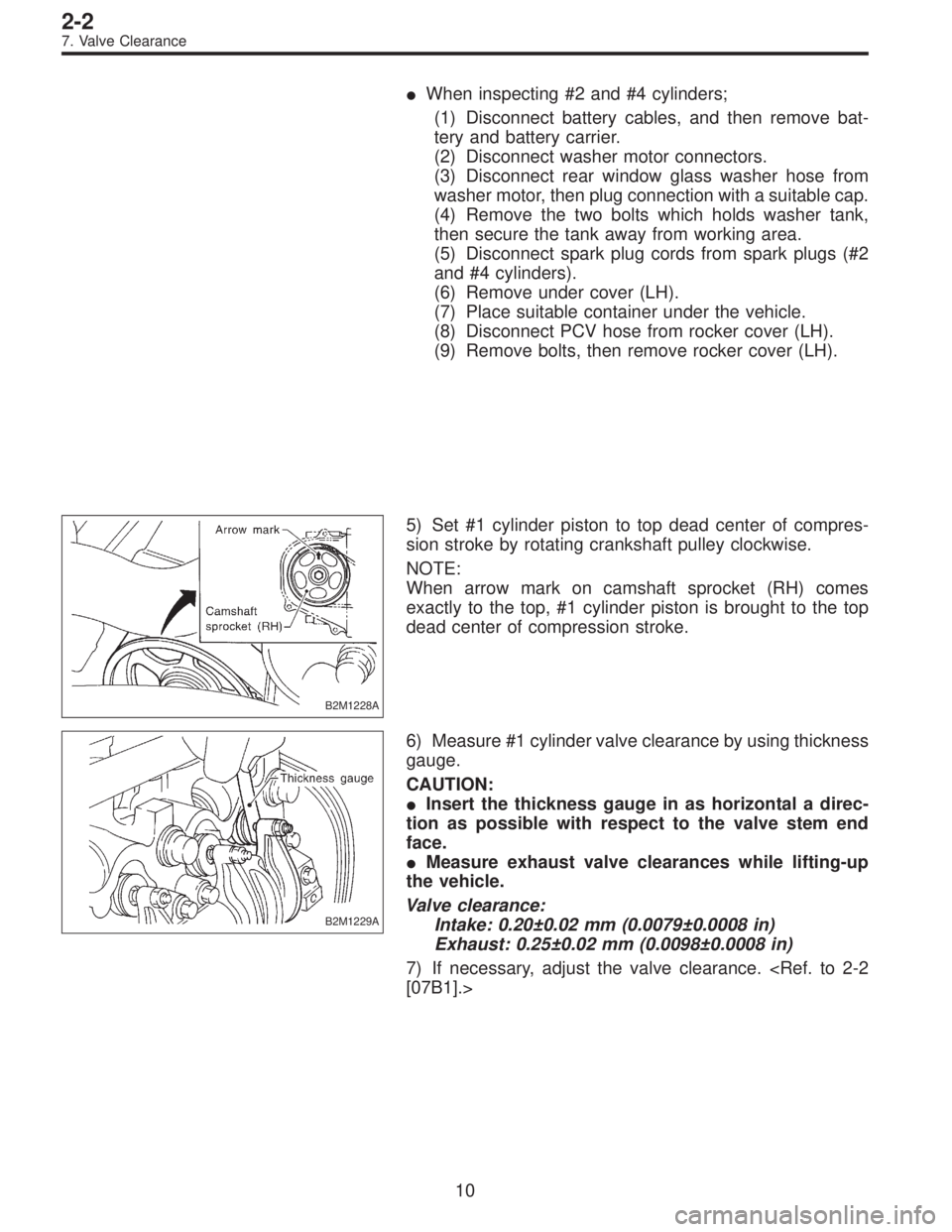
B2M1228A
5) Set #1 cylinder piston to top dead center of compres-
sion stroke by rotating crankshaft pulley clockwise.
NOTE:
When arrow mark on camshaft sprocket (RH) comes
exactly to the top, #1 cylinder piston is brought to the top
dead center of compression stroke.
B2M1229A
6) Measure #1 cylinder valve clearance by using thickness
gauge.
CAUTION:
�Insert the thickness gauge in as horizontal a direc-
tion as possible with respect to the valve stem end
face.
�Measure exhaust valve clearances while lifting-up
the vehicle.
Valve clearance:
Intake: 0.20±0.02 mm (0.0079±0.0008 in)
Exhaust: 0.25±0.02 mm (0.0098±0.0008 in)
7) If necessary, adjust the valve clearance.
[07B1].>
10
2-2
7. Valve Clearance
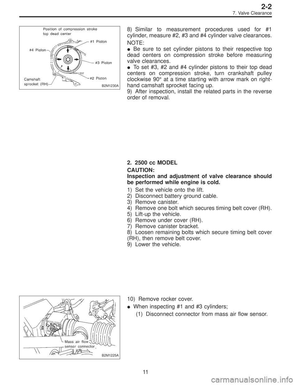
B2M1230A
8) Similar to measurement procedures used for #1
cylinder, measure #2, #3 and #4 cylinder valve clearances.
NOTE:
�Be sure to set cylinder pistons to their respective top
dead centers on compression stroke before measuring
valve clearances.
�To set #3, #2 and #4 cylinder pistons to their top dead
centers on compression stroke, turn crankshaft pulley
clockwise 90°at a time starting with arrow mark on right-
hand camshaft sprocket facing up.
9) After inspection, install the related parts in the reverse
order of removal.
2. 2500 cc MODEL
CAUTION:
Inspection and adjustment of valve clearance should
be performed while engine is cold.
1) Set the vehicle onto the lift.
2) Disconnect battery ground cable.
3) Remove canister.
4) Remove one bolt which secures timing belt cover (RH).
5) Lift-up the vehicle.
6) Remove under cover (RH).
7) Remove canister bracket.
8) Loosen remaining bolts which secure timing belt cover
(RH), then remove belt cover.
9) Lower the vehicle.
B2M1225A
10) Remove rocker cover.
�When inspecting #1 and #3 cylinders;
(1) Disconnect connector from mass air flow sensor.
11
2-2
7. Valve Clearance