Page 1383 of 3342
 Slowly depress the brake pedal and keep it
depressed. Then, open the air bleeder to discharge air
together with the fluid.
Release air bleeder for 1 to 2 seconds.
Next, with the bleeder closed, sl")
(2) Slowly depress the brake pedal and keep it
depressed. Then, open the air bleeder to discharge air
together with the fluid.
Release air bleeder for 1 to 2 seconds.
Next, with the bleeder closed, slowly release the brake
pedal.
Repeat these steps until there are no more air bubbles
in the vinyl tube.
Allow 3 to 4 seconds between two brake pedal opera-
tions.
CAUTION:
Cover bleeder with waste cloth, when loosening it, to
prevent brake fluid from being splashed over sur-
rounding parts.
NOTE:
Brake pedal operating must be very slow.
4) Bleed air from suction pipe through front RH caliper.
(1) Open the air bleeder.
(2) Keep pressing TCS OFF switch for 20 seconds or
more.
NOTE:
Ensure no air comes out from air bleeder.
(3) Close the air bleeder.
5) Bleed air through front LH caliper by operating brake
pedal. This is the same procedure as step 3).
6) Bleed air from suction pipe through front LH caliper.
This is the same procedure as step 4).
7) Bleed air through front RH and LH calipers by operat-
ing brake pedal. This is the same procedure as step 3).
Repeat steps 3) to 7) until air does no longer comes out.
8) Tighten air bleeders securely when bubbles are visible.
Air bleeder tightening torque:
8±1 N⋅m (0.8±0.1 kg-m, 5.8±0.7 ft-lb)
9) Bleed air through rear LH and RH caliper by operating
brake pedal. This is the same procedure as step 3).
10) Tighten air bleeders securely when bubbles are vis-
ible.
Air bleeder tightening torque:
8±1 N⋅m (0.8±0.1 kg-m, 5.8±0.7 ft-lb)
99
4-4SERVICE PROCEDURE
19. Air Bleeding (With TCS model)
Page 1389 of 3342
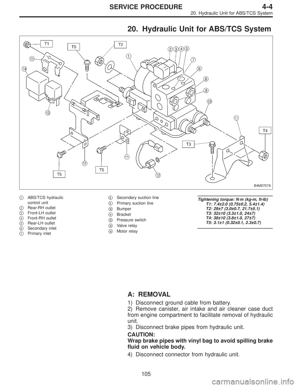
20. Hydraulic Unit for ABS/TCS System
B4M0707A
�1ABS/TCS hydraulic
control unit
�
2Rear-RH outlet
�
3Front-LH outlet
�
4Front-RH outlet
�
5Rear-LH outlet
�
6Secondary inlet
�
7Primary inlet�
8Secondary suction line
�
9Primary suction line
�
10Bumper
�
11Bracket
�
12Pressure switch
�
13Valve relay
�
14Motor relay
Tightening torque: N⋅m (kg-m, ft-lb)
T1: 7.4±2.0 (0.75±0.2, 5.4±1.4)
T2: 29±7 (3.0±0.7, 21.7±5.1)
T3: 32±10 (3.3±1.0, 24±7)
T4: 38±10 (3.8±1.0, 27±7)
T5: 3.1±1 (0.32±0.1, 2.3±0.7)
A: REMOVAL
1) Disconnect ground cable from battery.
2) Remove canister, air intake and air cleaner case duct
from engine compartment to facilitate removal of hydraulic
unit.
3) Disconnect brake pipes from hydraulic unit.
CAUTION:
Wrap brake pipes with vinyl bag to avoid spilling brake
fluid on vehicle body.
4) Disconnect connector from hydraulic unit.
105
4-4SERVICE PROCEDURE
20. Hydraulic Unit for ABS/TCS System
Page 1403 of 3342
B4M0628
G: INSTALLATION
1) Install hydraulic unit and bracket.
Tightening torque:
32±7 N⋅m (3.3±0.7 kg-m, 23.9±5.1 ft-lb)
2) Connect brake pipes to their correct hydraulic unit con-
nections.
3) Connect connector to hydraulic unit.
4) Install canister.
5) Install air cleaner case.
6) Install air intake duct.
7) Connect ground cable to battery.
CAUTION:
Cover relay securely with rubber boot.
21. ABS/TCS Control Module
A: REMOVAL
1) Disconnect ground cable from battery.
2) Remove floor mat located under lower right side of front
seat.
B4M0643A
3) Remove screw which secure ABS/TCS control module
from the body.
4) Disconnect connector from ABS/TCS control module.
B: INSPECTION
Check that connector is connected correctly and that con-
nector terminal sliding resistance is correct.
11 9
4-4SERVICE PROCEDURE
20. Hydraulic Unit for ABS/TCS System - 21. ABS/TCS Control Module
Page 1404 of 3342
B4M0628
G: INSTALLATION
1) Install hydraulic unit and bracket.
Tightening torque:
32±7 N⋅m (3.3±0.7 kg-m, 23.9±5.1 ft-lb)
2) Connect brake pipes to their correct hydraulic unit con-
nections.
3) Connect connector to hydraulic unit.
4) Install canister.
5) Install air cleaner case.
6) Install air intake duct.
7) Connect ground cable to battery.
CAUTION:
Cover relay securely with rubber boot.
21. ABS/TCS Control Module
A: REMOVAL
1) Disconnect ground cable from battery.
2) Remove floor mat located under lower right side of front
seat.
B4M0643A
3) Remove screw which secure ABS/TCS control module
from the body.
4) Disconnect connector from ABS/TCS control module.
B: INSPECTION
Check that connector is connected correctly and that con-
nector terminal sliding resistance is correct.
11 9
4-4SERVICE PROCEDURE
20. Hydraulic Unit for ABS/TCS System - 21. ABS/TCS Control Module
Page 1406 of 3342
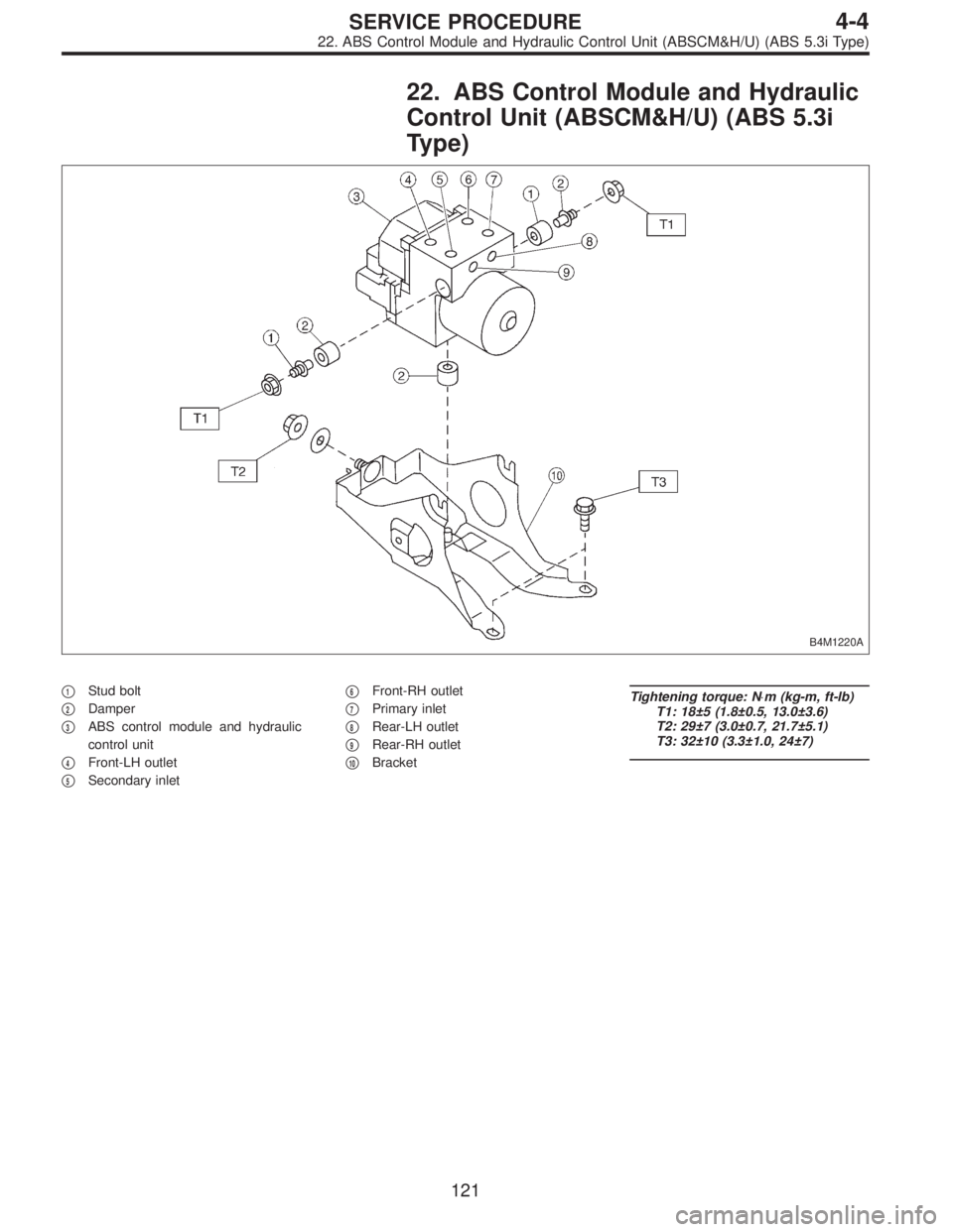
22. ABS Control Module and Hydraulic
Control Unit (ABSCM&H/U) (ABS 5.3i
Type)
B4M1220A
�1Stud bolt
�
2Damper
�
3ABS control module and hydraulic
control unit
�
4Front-LH outlet
�
5Secondary inlet�
6Front-RH outlet
�
7Primary inlet
�
8Rear-LH outlet
�
9Rear-RH outlet
�
10Bracket
Tightening torque: N⋅m (kg-m, ft-lb)
T1: 18±5 (1.8±0.5, 13.0±3.6)
T2: 29±7 (3.0±0.7, 21.7±5.1)
T3: 32±10 (3.3±1.0, 24±7)
121
4-4SERVICE PROCEDURE
22. ABS Control Module and Hydraulic Control Unit (ABSCM&H/U) (ABS 5.3i Type)
Page 1415 of 3342
B4M1222
E: INSTALLATION
1) Install ABSCM&H/U.
CAUTION:
Confirm that the specifications of the ABSCM&H/U
conforms to the vehicle specifications.
Tightening torque:
18±5 N⋅m (1.8±0.5 kg-m, 13.0±3.6 ft-lb)
2) Connect brake pipes to their correct ABSCM&H/U con-
nections.
3) Using cable clip, secure ABSCM&H/U harness to
bracket.
4) Connect connector to ABSCM&H/U.
CAUTION:
�Be sure to remove all foreign matter from inside the
connector before connecting.
�Ensure that the ABSCM&H/U connector is securely
locked.
5) Install air intake duct.
6) Connect ground cable to battery.
7) Bleed air from the brake system.
23. ABS Sensor (ABS 5.3i Type)
24. G Sensor (ABS 5.3i Type)
130
4-4SERVICE PROCEDURE
22. ABS Control Module and Hydraulic Control Unit (ABSCM&H/U) (ABS 5.3i Type) - 24. G Sensor (ABS 5.3i Type)
Page 1416 of 3342
B4M1222
E: INSTALLATION
1) Install ABSCM&H/U.
CAUTION:
Confirm that the specifications of the ABSCM&H/U
conforms to the vehicle specifications.
Tightening torque:
18±5 N⋅m (1.8±0.5 kg-m, 13.0±3.6 ft-lb)
2) Connect brake pipes to their correct ABSCM&H/U con-
nections.
3) Using cable clip, secure ABSCM&H/U harness to
bracket.
4) Connect connector to ABSCM&H/U.
CAUTION:
�Be sure to remove all foreign matter from inside the
connector before connecting.
�Ensure that the ABSCM&H/U connector is securely
locked.
5) Install air intake duct.
6) Connect ground cable to battery.
7) Bleed air from the brake system.
23. ABS Sensor (ABS 5.3i Type)
24. G Sensor (ABS 5.3i Type)
130
4-4SERVICE PROCEDURE
22. ABS Control Module and Hydraulic Control Unit (ABSCM&H/U) (ABS 5.3i Type) - 24. G Sensor (ABS 5.3i Type)
Page 1417 of 3342
B4M1222
E: INSTALLATION
1) Install ABSCM&H/U.
CAUTION:
Confirm that the specifications of the ABSCM&H/U
conforms to the vehicle specifications.
Tightening torque:
18±5 N⋅m (1.8±0.5 kg-m, 13.0±3.6 ft-lb)
2) Connect brake pipes to their correct ABSCM&H/U con-
nections.
3) Using cable clip, secure ABSCM&H/U harness to
bracket.
4) Connect connector to ABSCM&H/U.
CAUTION:
�Be sure to remove all foreign matter from inside the
connector before connecting.
�Ensure that the ABSCM&H/U connector is securely
locked.
5) Install air intake duct.
6) Connect ground cable to battery.
7) Bleed air from the brake system.
23. ABS Sensor (ABS 5.3i Type)
24. G Sensor (ABS 5.3i Type)
130
4-4SERVICE PROCEDURE
22. ABS Control Module and Hydraulic Control Unit (ABSCM&H/U) (ABS 5.3i Type) - 24. G Sensor (ABS 5.3i Type)
 Install hydraulic unit and bracket.
Tightening torque:
32±7 N⋅m (3.3±0.7 kg-m, 23.9±5.1 ft-lb)
2) Connect brake pipes to their correct hydraulic unit con-
nections. <Re")
 Install hydraulic unit and bracket.
Tightening torque:
32±7 N⋅m (3.3±0.7 kg-m, 23.9±5.1 ft-lb)
2) Connect brake pipes to their correct hydraulic unit con-
nections. <Re")
 Install ABSCM&H/U.
CAUTION:
Confirm that the specifications of the ABSCM&H/U
conforms to the vehicle specifications.
Tightening torque:
18±5 N⋅m (1.8±0.5 kg-m, 13.0±3.6")
 Install ABSCM&H/U.
CAUTION:
Confirm that the specifications of the ABSCM&H/U
conforms to the vehicle specifications.
Tightening torque:
18±5 N⋅m (1.8±0.5 kg-m, 13.0±3.6")
 Install ABSCM&H/U.
CAUTION:
Confirm that the specifications of the ABSCM&H/U
conforms to the vehicle specifications.
Tightening torque:
18±5 N⋅m (1.8±0.5 kg-m, 13.0±3.6")