Page 1307 of 3342
1. Front Disc Brake
B4M0065B
�1Air bleeder screw
�
2Guide pin
�
3Guide pin boot
�
4Piston
�
5Piston seal
�
6Piston boot
�
7Lock pin boot
�
8Lock pin sleeve
�
9Caliper body�
10Lock pin
�
11Housing
�
12Support
�
13Pad clip
�
14Outer shim
�
15Outer pad
�
16Inner pad
�
17Inner shim
�
18Shim�
19Disc rotor
�
20Disc cover
Tightening torque: N⋅m (kg-m, ft-lb)
T1: 8±1 (0.8±0.1, 5.8±0.7)
T2: 18±5 (1.8±0.5, 13.0±3.6)
T3: 39±5 (4±0.5, 28.9±3.6)
T4: 78±10 (8.0±1.0, 58±7)
27
4-4SERVICE PROCEDURE
1. Front Disc Brake
Page 1310 of 3342
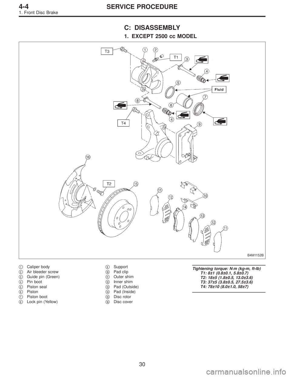
C: DISASSEMBLY
1. EXCEPT 2500 cc MODEL
B4M1152B
�1Caliper body
�
2Air bleeder screw
�
3Guide pin (Green)
�
4Pin boot
�
5Piston seal
�
6Piston
�
7Piston boot
�
8Lock pin (Yellow)�
9Support
�
10Pad clip
�
11Outer shim
�
12Inner shim
�
13Pad (Outside)
�
14Pad (Inside)
�
15Disc rotor
�
16Disc cover
Tightening torque: N⋅m (kg-m, ft-lb)
T1: 8±1 (0.8±0.1, 5.8±0.7)
T2: 18±5 (1.8±0.5, 13.0±3.6)
T3: 37±5 (3.8±0.5, 27.5±3.6)
T4: 78±10 (8.0±1.0, 58±7)
30
4-4SERVICE PROCEDURE
1. Front Disc Brake
Page 1312 of 3342
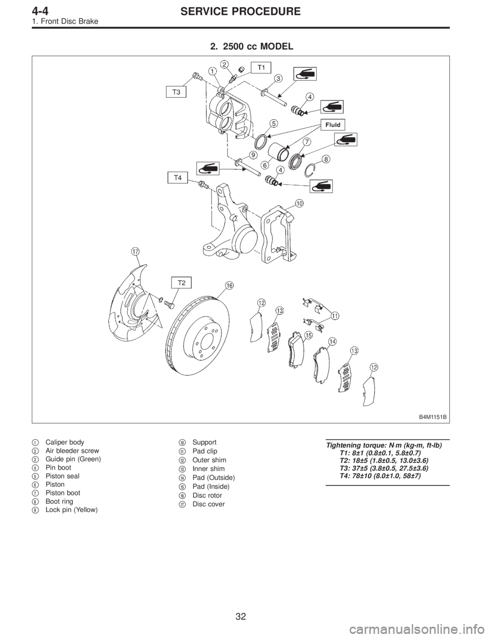
2. 2500 cc MODEL
B4M1151B
�1Caliper body
�
2Air bleeder screw
�
3Guide pin (Green)
�
4Pin boot
�
5Piston seal
�
6Piston
�
7Piston boot
�
8Boot ring
�
9Lock pin (Yellow)�
10Support
�
11Pad clip
�
12Outer shim
�
13Inner shim
�
14Pad (Outside)
�
15Pad (Inside)
�
16Disc rotor
�
17Disc cover
Tightening torque: N⋅m (kg-m, ft-lb)
T1: 8±1 (0.8±0.1, 5.8±0.7)
T2: 18±5 (1.8±0.5, 13.0±3.6)
T3: 37±5 (3.8±0.5, 27.5±3.6)
T4: 78±10 (8.0±1.0, 58±7)
32
4-4SERVICE PROCEDURE
1. Front Disc Brake
Page 1316 of 3342
 Install disc rotor on hub.
2) Install support on housing.
Tightening torque:
78±10 N⋅m (8±1 kg-m, 58±7 ft-lb)
CAUTION:
�Always replace the pads for both the left and right
whee")
F: INSTALLATION
1) Install disc rotor on hub.
2) Install support on housing.
Tightening torque:
78±10 N⋅m (8±1 kg-m, 58±7 ft-lb)
CAUTION:
�Always replace the pads for both the left and right
wheels at the same time. Also replace pad clips if they
are twisted or worn.
�A wear indicator is provided on the inner disc brake
pad. If the pad wears down to such an extent that the
end of the wear indicator contacts the disc rotor, a
squeaking sound is produced as the wheel rotates. If
this sound is heard, replace the pad.
�When replacing the pad, replace pads of the right
and left wheels at the same time.
B4M1169A
3) Apply thin coat of PBC GREASE (Part No. 003607000)
to the frictional portion between pad and pad clip.
4) Install pads, rubber coated shim and stainless shim on
support.
5) Install caliper body on support.
Tightening torque:
39±5 N⋅m (4±0.5 kg-m, 28.9±3.6 ft-lb)
6) Connect brake hose.
Tightening torque:
18±3 N⋅m (1.8±0.3 kg-m, 13.0±2.2 ft-lb)
CAUTION:
Replace brake hose gaskets with new ones.
7) Bleed air from brake system.
36
4-4SERVICE PROCEDURE
1. Front Disc Brake
Page 1317 of 3342
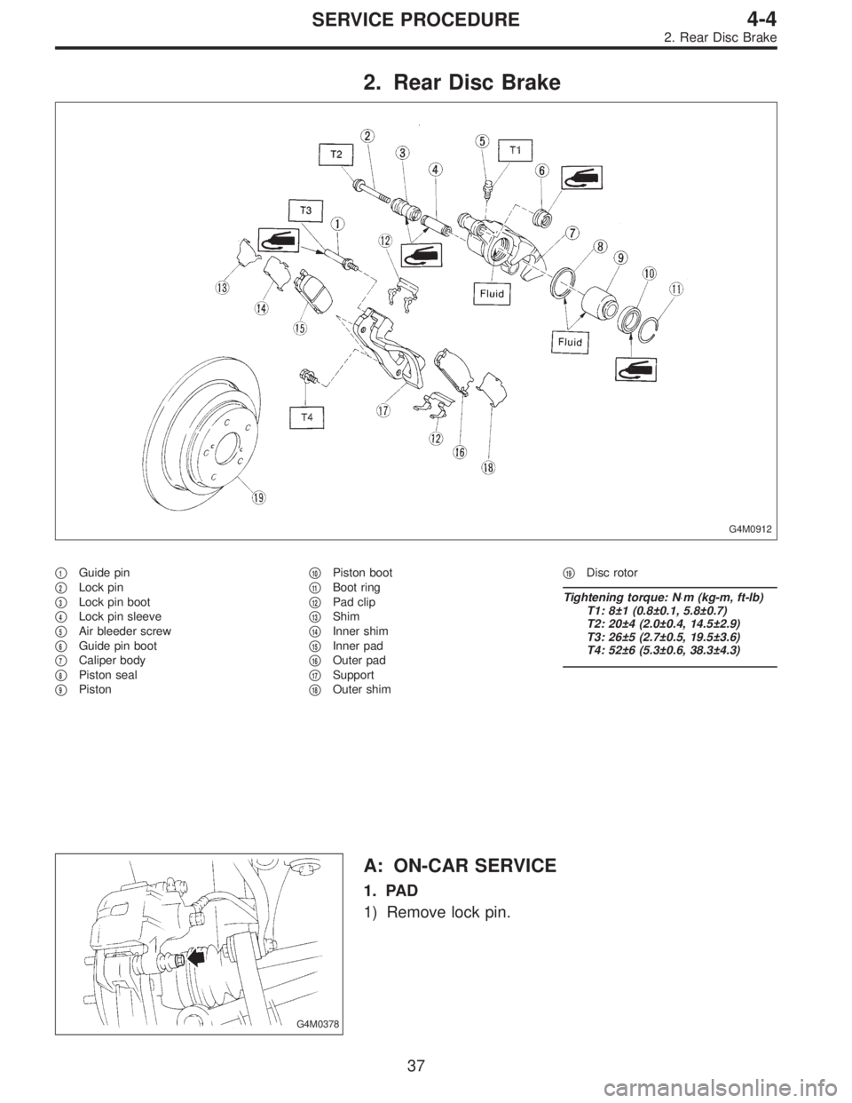
2. Rear Disc Brake
G4M0912
�1Guide pin
�
2Lock pin
�
3Lock pin boot
�
4Lock pin sleeve
�
5Air bleeder screw
�
6Guide pin boot
�
7Caliper body
�
8Piston seal
�
9Piston�
10Piston boot
�
11Boot ring
�
12Pad clip
�
13Shim
�
14Inner shim
�
15Inner pad
�
16Outer pad
�
17Support
�
18Outer shim�
19Disc rotor
Tightening torque: N⋅m (kg-m, ft-lb)
T1: 8±1 (0.8±0.1, 5.8±0.7)
T2: 20±4 (2.0±0.4, 14.5±2.9)
T3: 26±5 (2.7±0.5, 19.5±3.6)
T4: 52±6 (5.3±0.6, 38.3±4.3)
G4M0378
A: ON-CAR SERVICE
1. PAD
1) Remove lock pin.
37
4-4SERVICE PROCEDURE
2. Rear Disc Brake
Page 1318 of 3342
 Raise caliper body.
3) Remove pad from support.
G4M0362
4) Check pad thickness (including back metal).
Pad thickness: A
Standard value 15.0 mm (0.591 in)
Wear limit 6.5 mm (0.256 in)
CAUTIO")
G4M0379
2) Raise caliper body.
3) Remove pad from support.
G4M0362
4) Check pad thickness (including back metal).
Pad thickness: A
Standard value 15.0 mm (0.591 in)
Wear limit 6.5 mm (0.256 in)
CAUTION:
�Always replace the pads for both the left and right
wheels at the same time. Also replace pad clips if they
are twisted or worn.
�A wear indicator is provided on the inner disc brake
pad. If the pad wears down to such an extent that the
end of the wear indicator contacts the disc rotor, a
squeaking sound is produced as the wheel rotates. If
this sound is heard, replace the pad.
�Replace pad if there is oil or grease on it.
G4M0363
5) Apply thin coat of PBC GREASE (Part No. 03607000)
to the frictional portion between pad and pad clip.
6) Install pad on support.
7) Install caliper body on support.
Tightening torque:
20±4 N⋅m (2.0±0.4 kg-m, 14.5±2.9 ft-lb)
NOTE:
If it is difficult to push piston during pad replacement,
loosen air bleeder to facilitate work.
38
4-4SERVICE PROCEDURE
2. Rear Disc Brake
Page 1322 of 3342
 Install disc rotor on hub.
2) Install support on back plate.
Tightening torque:
52±6 N⋅m (5.3±0.6 kg-m, 38.3±4.3 ft-lb)
CAUTION:
�Always replace the pads for both the left and")
F: INSTALLATION
1) Install disc rotor on hub.
2) Install support on back plate.
Tightening torque:
52±6 N⋅m (5.3±0.6 kg-m, 38.3±4.3 ft-lb)
CAUTION:
�Always replace the pads for both the left and right
wheels at the same time. Also replace pad clips if they
are twisted or worn.
�A wear indicator is provided on the inner disc brake
pad. If the pad wears down to such an extent that the
end of the wear indicator contacts the disc rotor, a
squeaking sound is produced as the wheel rotates. If
this sound is heard, replace the pad.
�Replace pads if there is oil or grease on them.
3) Apply thin coat of PBC GREASE (Part No. 003607000)
to the frictional portion between pad and pad clip.
G4M0363
4) Install pads on support.
5) Install caliper body on support.
Tightening torque:
20±4 N⋅m (2.0±0.4 kg-m, 14.5±2.9 ft-lb)
6) Connect brake hose.
Tightening torque:
18±3 N⋅m (1.8±0.3 kg-m, 13.0±2.2 ft-lb)
CAUTION:
�The brake hose must be connected without any
twist.
�Replace brake hose gaskets with new ones.
7) Bleed air from brake system.
42
4-4SERVICE PROCEDURE
2. Rear Disc Brake
Page 1323 of 3342
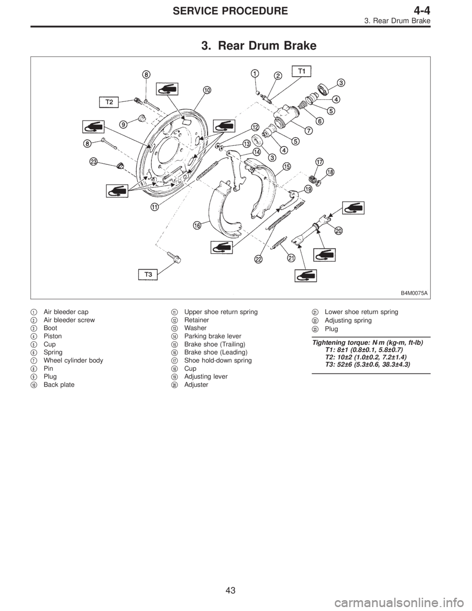
3. Rear Drum Brake
B4M0075A
�1Air bleeder cap
�
2Air bleeder screw
�
3Boot
�
4Piston
�
5Cup
�
6Spring
�
7Wheel cylinder body
�
8Pin
�
9Plug
�
10Back plate�
11Upper shoe return spring
�
12Retainer
�
13Washer
�
14Parking brake lever
�
15Brake shoe (Trailing)
�
16Brake shoe (Leading)
�
17Shoe hold-down spring
�
18Cup
�
19Adjusting lever
�
20Adjuster�
21Lower shoe return spring
�
22Adjusting spring
�
23Plug
Tightening torque: N⋅m (kg-m, ft-lb)
T1: 8±1 (0.8±0.1, 5.8±0.7)
T2: 10±2 (1.0±0.2, 7.2±1.4)
T3: 52±6 (5.3±0.6, 38.3±4.3)
43
4-4SERVICE PROCEDURE
3. Rear Drum Brake