Page 1359 of 3342
3) Install rear drive shaft to rear housing and rear differen-
tial spindle.
G4M0453
4) Install rear sensor harness on rear trailing link.
Tightening torque:
32±10 N⋅m (3.3±1.0 kg-m, 24±7 ft-lb)
5) Place a thickness gauge between ABS sensor’s pole
piece and tone wheel’s tooth face. After standard clearance
is obtained over the entire perimeter, tighten ABS sensor
on back plate to specified torque.
ABS sensor standard clearance:
0.7—1.2 mm (0.028—0.047 in)
Tightening torque:
32±10 N⋅m (3.3±1.0 kg-m, 24±7 ft-lb)
CAUTION:
Check the marks on the harness to make sure that no
distortion exists. (RH: white, LH: yellow)
NOTE:
If the clearance is outside specifications, readjust.
77
4-4SERVICE PROCEDURE
14. ABS Sensor
Page 1360 of 3342
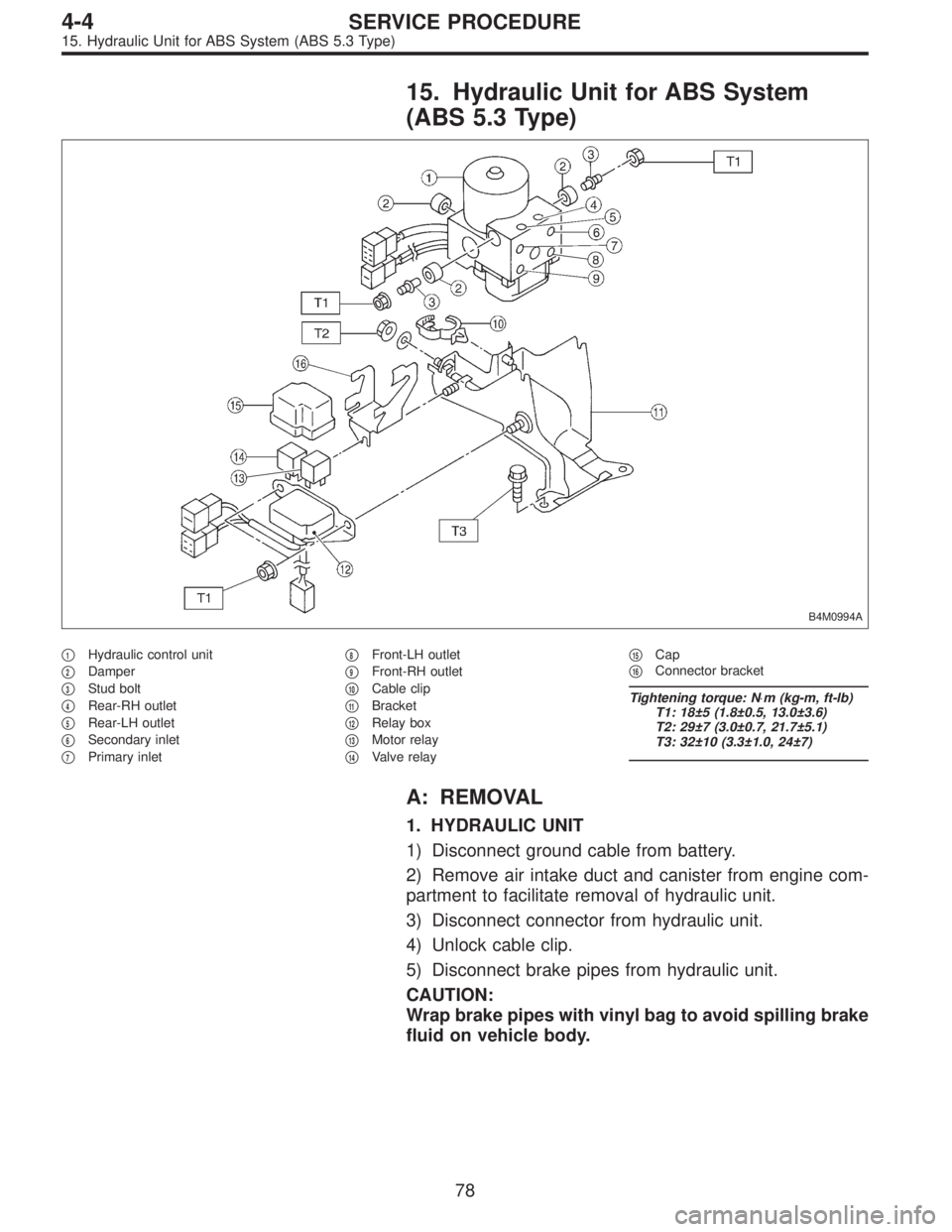
15. Hydraulic Unit for ABS System
(ABS 5.3 Type)
B4M0994A
�1Hydraulic control unit
�
2Damper
�
3Stud bolt
�
4Rear-RH outlet
�
5Rear-LH outlet
�
6Secondary inlet
�
7Primary inlet�
8Front-LH outlet
�
9Front-RH outlet
�
10Cable clip
�
11Bracket
�
12Relay box
�
13Motor relay
�
14Valve relay�
15Cap
�
16Connector bracket
Tightening torque: N⋅m (kg-m, ft-lb)
T1: 18±5 (1.8±0.5, 13.0±3.6)
T2: 29±7 (3.0±0.7, 21.7±5.1)
T3: 32±10 (3.3±1.0, 24±7)
A: REMOVAL
1. HYDRAULIC UNIT
1) Disconnect ground cable from battery.
2) Remove air intake duct and canister from engine com-
partment to facilitate removal of hydraulic unit.
3) Disconnect connector from hydraulic unit.
4) Unlock cable clip.
5) Disconnect brake pipes from hydraulic unit.
CAUTION:
Wrap brake pipes with vinyl bag to avoid spilling brake
fluid on vehicle body.
78
4-4SERVICE PROCEDURE
15. Hydraulic Unit for ABS System (ABS 5.3 Type)
Page 1369 of 3342
B4M0996
E: INSTALLATION
1. HYDRAULIC UNIT
1) Install hydraulic unit.
Tightening torque:
18±5 N⋅m (1.8±0.5 kg-m, 13.0±3.6 ft-lb)
2) Connect hydraulic unit ground cable to body.
Tightening torque:
32±10 N⋅m (3.3±1.0 kg-m, 24±7 ft-lb)
3) Connect brake pipes to their correct hydraulic unit con-
nections.
B4M1031A
4) Secure hydraulic unit connector to connector bracket.
CAUTION:
Align connector wit mating receptacle.
5) Using cable clip, secure hydraulic unit harness to relay
box harness.
CAUTION:
Make sure hydraulic unit harness band is secured
beneath cable clip.
6) Connect connector to hydraulic unit.
7) Install canister.
8) Install air intake duct.
9) Connect ground cable to battery.
10) Bleed air from the brake system.
B4M1029
2. RELAY BOX
1) Install relay box and connector bracket.
Tightening torque:
18±5 N⋅m (1.8±0.5 kg-m, 13.0±3.6 ft-lb)
87
4-4SERVICE PROCEDURE
15. Hydraulic Unit for ABS System (ABS 5.3 Type)
Page 1377 of 3342

18. Brake Hose and Pipe
SUPPLEMENTAL RESTRAINT SYSTEM“AIRBAG”
Airbag system wiring harness is routed near the center
brake pipe.
CAUTION:
�All Airbag system wiring harness and connectors
are colored yellow. Do not use electrical test equip-
ment on these circuit.
�Be careful not to damage Airbag system wiring har-
ness when servicing the center brake pipe.
A: REMOVAL AND INSTALLATION
CAUTION:
�When removing and installing the brake pipe, make
sure that it is not bent.
�After installing the brake pipe and hose, bleed the
air.
�After installing the brake hose, make sure that it
does not touch the tire or suspension assembly, etc.
1. MODELS WITHOUT ABS
G4M0472
�1Union bolt
�
2Front brake hose RH
�
3Proportioning valve
�
4Front brake pipe
�
5Front adapter pipe (UPPER)
�
6Front adapter pipe (LOWER)
�
7Front brake hose LH�
8Center brake pipe ASSY
�
9Connector bracket
�
10Two-way connector
�
11Rear brake pipe RH
�
12Rear brake hose drum
�
13Rear brake pipe ASSY
�
14Rear brake pipe LH
Tightening torque: N⋅m (kg-m, ft-lb)
T1: 13±3 (1.3±0.3, 9.4±2.2)
T2: 15
+3
�2(1.5+0.3
�0.2, 10.8+2.2
�1.4)
T3: 18±3 (1.8±0.3, 13.0±2.2)
T4: 18±5 (1.8±0.5, 13.0±3.6)
93
4-4SERVICE PROCEDURE
18. Brake Hose and Pipe
Page 1378 of 3342
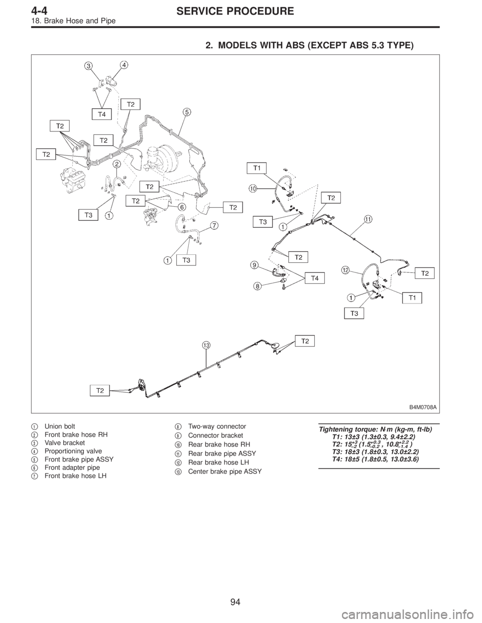
2. MODELS WITH ABS (EXCEPT ABS 5.3 TYPE)
B4M0708A
�1Union bolt
�
2Front brake hose RH
�
3Valve bracket
�
4Proportioning valve
�
5Front brake pipe ASSY
�
6Front adapter pipe
�
7Front brake hose LH�
8Two-way connector
�
9Connector bracket
�
10Rear brake hose RH
�
11Rear brake pipe ASSY
�
12Rear brake hose LH
�
13Center brake pipe ASSY
Tightening torque: N⋅m (kg-m, ft-lb)
T1: 13±3 (1.3±0.3, 9.4±2.2)
T2: 15
+3
�2(1.5+0.3
�0.2, 10.8+2.2
�1.4)
T3: 18±3 (1.8±0.3, 13.0±2.2)
T4: 18±5 (1.8±0.5, 13.0±3.6)
94
4-4SERVICE PROCEDURE
18. Brake Hose and Pipe
Page 1379 of 3342
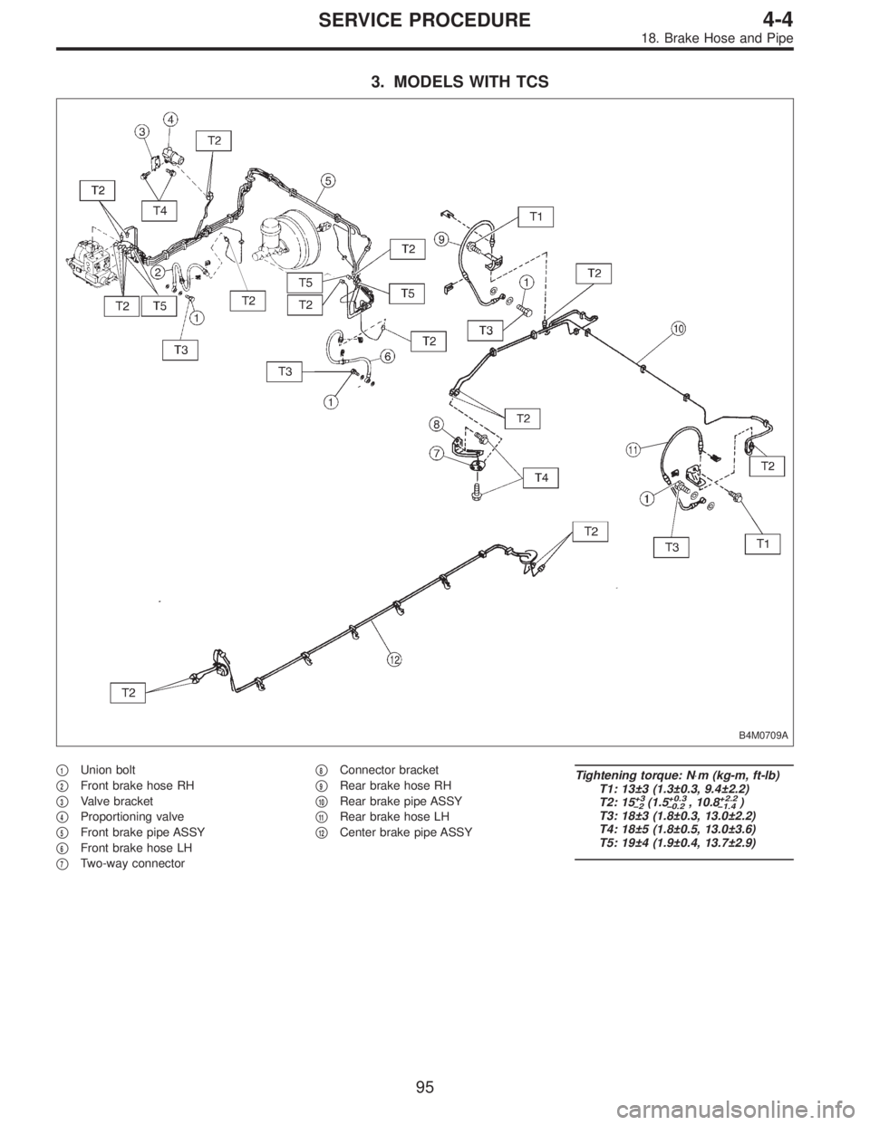
3. MODELS WITH TCS
B4M0709A
�1Union bolt
�
2Front brake hose RH
�
3Valve bracket
�
4Proportioning valve
�
5Front brake pipe ASSY
�
6Front brake hose LH
�
7Two-way connector�
8Connector bracket
�
9Rear brake hose RH
�
10Rear brake pipe ASSY
�
11Rear brake hose LH
�
12Center brake pipe ASSY
Tightening torque: N⋅m (kg-m, ft-lb)
T1: 13±3 (1.3±0.3, 9.4±2.2)
T2: 15
+3
�2(1.5+0.3
�0.2, 10.8+2.2
�1.4)
T3: 18±3 (1.8±0.3, 13.0±2.2)
T4: 18±5 (1.8±0.5, 13.0±3.6)
T5: 19±4 (1.9±0.4, 13.7±2.9)
95
4-4SERVICE PROCEDURE
18. Brake Hose and Pipe
Page 1380 of 3342
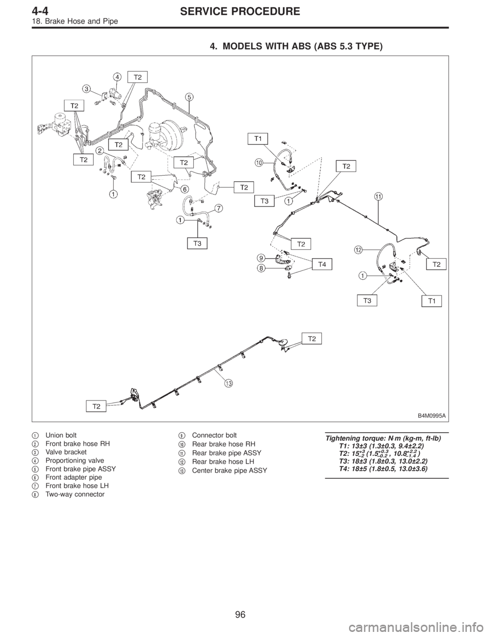
4. MODELS WITH ABS (ABS 5.3 TYPE)
B4M0995A
�1Union bolt
�
2Front brake hose RH
�
3Valve bracket
�
4Proportioning valve
�
5Front brake pipe ASSY
�
6Front adapter pipe
�
7Front brake hose LH
�
8Two-way connector�
9Connector bolt
�
10Rear brake hose RH
�
11Rear brake pipe ASSY
�
12Rear brake hose LH
�
13Center brake pipe ASSY
Tightening torque: N⋅m (kg-m, ft-lb)
T1: 13±3 (1.3±0.3, 9.4±2.2)
T2: 15
+3
�2(1.5+0.3
�0.2, 10.8+2.2
�1.4)
T3: 18±3 (1.8±0.3, 13.0±2.2)
T4: 18±5 (1.8±0.5, 13.0±3.6)
96
4-4SERVICE PROCEDURE
18. Brake Hose and Pipe
Page 1381 of 3342
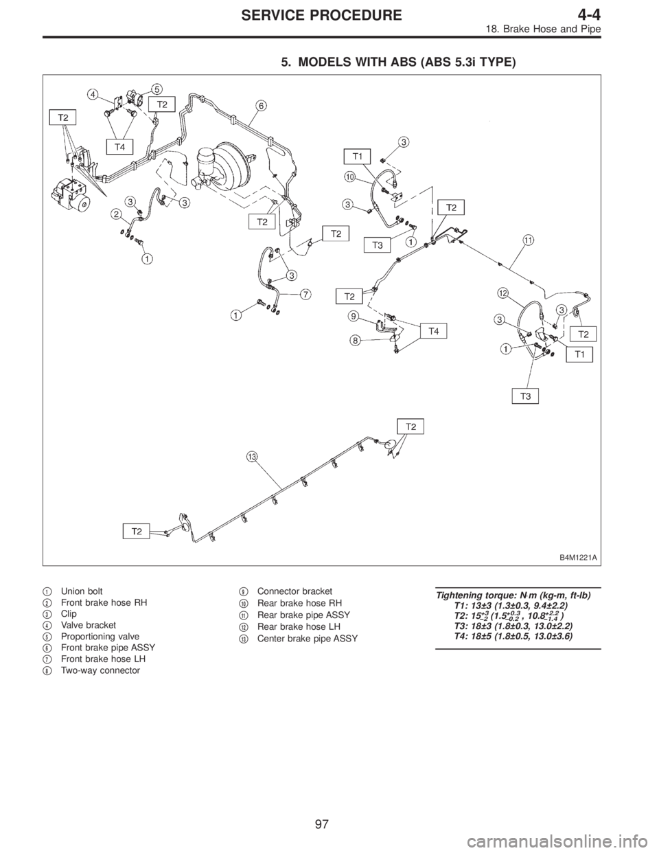
5. MODELS WITH ABS (ABS 5.3i TYPE)
B4M1221A
�1Union bolt
�
2Front brake hose RH
�
3Clip
�
4Valve bracket
�
5Proportioning valve
�
6Front brake pipe ASSY
�
7Front brake hose LH
�
8Two-way connector�
9Connector bracket
�
10Rear brake hose RH
�
11Rear brake pipe ASSY
�
12Rear brake hose LH
�
13Center brake pipe ASSY
Tightening torque: N⋅m (kg-m, ft-lb)
T1: 13±3 (1.3±0.3, 9.4±2.2)
T2: 15
+3
�2(1.5+0.3
�0.2, 10.8+2.2
�1.4)
T3: 18±3 (1.8±0.3, 13.0±2.2)
T4: 18±5 (1.8±0.5, 13.0±3.6)
97
4-4SERVICE PROCEDURE
18. Brake Hose and Pipe
![SUBARU LEGACY 1997 Service Repair Manual 3) Install rear drive shaft to rear housing and rear differen-
tial spindle. <Ref. to 4-2 [W2E0].>
G4M0453
4) Install rear sensor harness on rear trailing link.
Tightening torque:
32±10 N⋅m (3.3±1](/manual-img/17/57434/w960_57434-1358.png "SUBARU LEGACY 1997 Service Repair Manual 3) Install rear drive shaft to rear housing and rear differen-
tial spindle. <Ref. to 4-2 [W2E0].>
G4M0453
4) Install rear sensor harness on rear trailing link.
Tightening torque:
32±10 N⋅m (3.3±1")
 Install hydraulic unit.
Tightening torque:
18±5 N⋅m (1.8±0.5 kg-m, 13.0±3.6 ft-lb)
2) Connect hydraulic unit ground cable to body.
Tightening torque:")