Page 986 of 3342

G3M0434
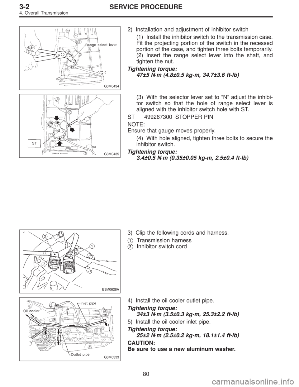
2) Installation and adjustment of inhibitor switch
(1) Install the inhibitor switch to the transmission case.
Fit the projecting portion of the switch in the recessed
portion of the case, and tighten three bolts temporarily.
(2) Insert the range select lever into the shaft, and
tighten the nut.
Tightening torque:
47±5 N⋅m (4.8±0.5 kg-m, 34.7±3.6 ft-lb)
G3M0435
(3) With the selector lever set to“N”adjust the inhibi-
tor switch so that the hole of range select lever is
aligned with the inhibitor switch hole with ST.
ST 499267300 STOPPER PIN
NOTE:
Ensure that gauge moves properly.
(4) With hole aligned, tighten three bolts to secure the
inhibitor switch.
Tightening torque:
3.4±0.5 N⋅m (0.35±0.05 kg-m, 2.5±0.4 ft-lb)
B3M0628A
3) Clip the following cords and harness.
�
1Transmission harness
�
2Inhibitor switch cord
G3M0333
4) Install the oil cooler outlet pipe.
Tightening torque:
34±3 N⋅m (3.5±0.3 kg-m, 25.3±2.2 ft-lb)
5) Install the oil cooler inlet pipe.
Tightening torque:
25±2 N⋅m (2.5±0.2 kg-m, 18.1±1.4 ft-lb)
CAUTION:
Be sure to use a new aluminum washer.
80
3-2SERVICE PROCEDURE
4. Overall Transmission
Page 987 of 3342
G3M0332
6) Install the oil charge pipe.
Tightening torque:
Upper
41±3 N⋅m (4.2±0.3 kg-m, 30.4±2.2 ft-lb)
Lower
6.4±0.5 N⋅m (0.65±0.05 kg-m, 4.7±0.4 ft-lb)
CAUTION:
Be careful not to damage the O-ring.
G3M0348
7) Adjustment of brake band
After tightening the brake band adjusting screw with ST
to9N⋅m (0.9 kg-m, 6.5 ft-lb) torque, back it off three
turns. Then secure with a lock nut.
ST 398603610 SOCKET WRENCH
Tightening torque:
26±2 N⋅m (2.7±0.2 kg-m, 19.5±1.4 ft-lb)
NOTE:
When tightening the lock nut, be careful not to turn the
adjusting screw.
B3M0636A
8) Install the air breather hose.
�
1Air breather hose (Transmission case)
�
2Air breather hose (Oil pump housing)
B3M0629
9) Install the pitching stopper bracket.
Tightening torque:
41±3 N⋅m (4.2±0.3 kg-m, 30.4±2.2 ft-lb)
G3M0325
10) Tighten the drain plugs.
Tightening torque:
Diff.
44±3 N⋅m (4.5±0.3 kg-m, 32.5±2.2 ft-lb)
AT F
25±2 N⋅m (2.5±0.2 kg-m, 18.1±1.4 ft-lb)
81
3-2SERVICE PROCEDURE
4. Overall Transmission
Page 988 of 3342

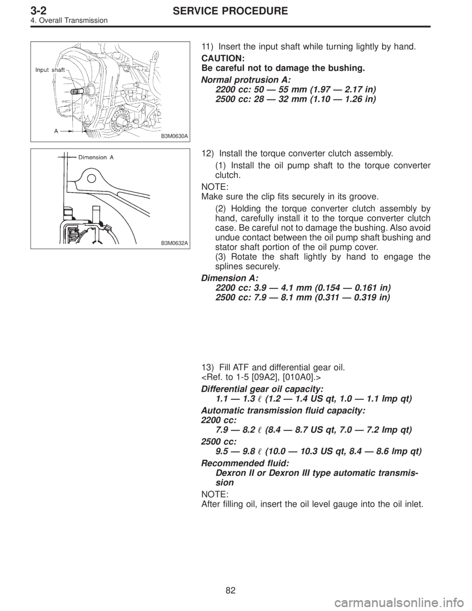
B3M0630A
11) Insert the input shaft while turning lightly by hand.
CAUTION:
Be careful not to damage the bushing.
Normal protrusion A:
2200 cc: 50—55 mm (1.97—2.17 in)
2500 cc: 28—32 mm (1.10—1.26 in)
B3M0632A
12) Install the torque converter clutch assembly.
(1) Install the oil pump shaft to the torque converter
clutch.
NOTE:
Make sure the clip fits securely in its groove.
(2) Holding the torque converter clutch assembly by
hand, carefully install it to the torque converter clutch
case. Be careful not to damage the bushing. Also avoid
undue contact between the oil pump shaft bushing and
stator shaft portion of the oil pump cover.
(3) Rotate the shaft lightly by hand to engage the
splines securely.
Dimension A:
2200 cc: 3.9—4.1 mm (0.154—0.161 in)
2500 cc: 7.9—8.1 mm (0.311—0.319 in)
13) Fill ATF and differential gear oil.
Differential gear oil capacity:
1.1—1.3�(1.2—1.4 US qt, 1.0—1.1 Imp qt)
Automatic transmission fluid capacity:
2200 cc:
7.9—8.2�(8.4—8.7 US qt, 7.0—7.2 Imp qt)
2500 cc:
9.5—9.8�(10.0—10.3 US qt, 8.4—8.6 lmp qt)
Recommended fluid:
Dexron II or Dexron III type automatic transmis-
sion
NOTE:
After filling oil, insert the oil level gauge into the oil inlet.
82
3-2SERVICE PROCEDURE
4. Overall Transmission
Page 991 of 3342

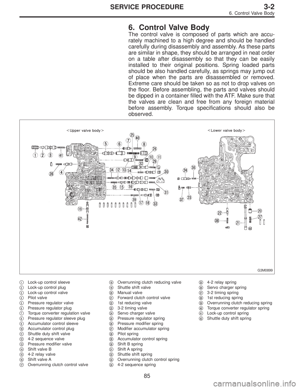
6. Control Valve Body
The control valve is composed of parts which are accu-
rately machined to a high degree and should be handled
carefully during disassembly and assembly. As these parts
are similar in shape, they should be arranged in neat order
on a table after disassembly so that they can be easily
installed to their original positions. Spring loaded parts
should be also handled carefully, as springs may jump out
of place when the parts are disassembled or removed.
Extreme care should be taken so as not to drop valves on
the floor. Before assembling, the parts and valves should
be dipped in a container filled with the ATF. Make sure that
the valves are clean and free from any foreign material
before assembly. Torque specifications should also be
observed.
G3M0899
�1Lock-up control sleeve
�
2Lock-up control plug
�
3Lock-up control valve
�
4Pilot valve
�
5Pressure regulator valve
�
6Pressure regulator plug
�
7Torque converter regulation valve
�
8Pressure regulator sleeve plug
�
9Accumulator control sleeve
�
10Accumulator control plug
�
11Shuttle duty shift valve
�
124-2 sequence valve
�
13Pressure modifier valve
�
14Shift valve B
�
154-2 relay valve
�
16Shift valve A
�
17Overrunning clutch control valve�
18Overrunning clutch reducing valve
�
19Shuttle shift valve
�
20Manual valve
�
21Forward clutch control valve
�
221st reducing valve
�
233-2 timing valve
�
24Servo charger valve
�
25Pressure regulator spring
�
26Pressure modifier spring
�
27Modifier accumulator spring
�
28Pilot spring
�
29Accumulator control spring
�
30Shift B spring
�
31Shift A spring
�
32Shuttle shift spring
�
33Overrunning clutch control spring
�
344-2 sequence spring�
354-2 relay spring
�
36Servo charger spring
�
373-2 timing spring
�
381st reducing spring
�
39Overrunning clutch reducing spring
�
40Torque converter regulator spring
�
41Lock-up control spring
�
42Shuttle duty shift spring
85
3-2SERVICE PROCEDURE
6. Control Valve Body
Page 992 of 3342

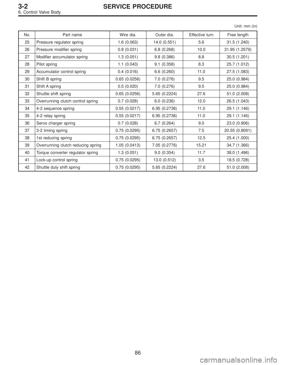
Unit: mm (in)
No. Part name Wire dia. Outer dia. Effective turn Free length
25 Pressure regulator spring 1.6 (0.063) 14.0 (0.551) 5.6 31.5 (1.240)
26 Pressure modifier spring 0.8 (0.031) 6.8 (0.268) 10.0 31.95 (1.2579)
27 Modifier accumulator spring 1.3 (0.051) 9.8 (0.386) 8.8 30.5 (1.201)
28 Pilot spring 1.1 (0.043) 9.1 (0.358) 8.3 25.7 (1.012)
29 Accumulator control spring 0.4 (0.016) 6.6 (0.260) 11.0 27.5 (1.083)
30 Shift B spring 0.65 (0.0256) 7.0 (0.276) 9.5 25.0 (0.984)
31 Shift A spring 0.5 (0.020) 7.0 (0.276) 9.5 25.0 (0.984)
32 Shuttle shift spring 0.65 (0.0256) 5.65 (0.2224) 27.6 51.0 (2.008)
33 Overrunning clutch control spring 0.7 (0.028) 6.0 (0.236) 12.0 26.5 (1.043)
34 4-2 sequence spring 0.55 (0.0217) 6.95 (0.2736) 11.0 29.1 (1.146)
35 4-2 relay spring 0.55 (0.0217) 6.95 (0.2736) 11.0 29.1 (1.146)
36 Servo charger spring 0.7 (0.028) 6.7 (0.264) 9.0 23.0 (0.906)
37 3-2 timing spring 0.75 (0.0295) 6.75 (0.2657) 7.5 20.55 (0.8091)
38 1st reducing spring 0.75 (0.0295) 6.75 (0.2657) 12.5 25.4 (1.000)
39 Overrunning clutch reducing spring 1.05 (0.0413) 7.05 (0.2776) 15.21 34.7 (1.366)
40 Torque converter regulator spring 1.3 (0.051) 9.0 (0.354) 11.7 38.0 (1.496)
41 Lock-up control spring 0.75 (0.0295) 13.0 (0.512) 3.5 18.5 (0.728)
42 Shuttle duty shift spring 0.75 (0.0295) 5.65 (0.2224) 27.6 51.0 (2.008)
86
3-2SERVICE PROCEDURE
6. Control Valve Body
Page 995 of 3342
G3M0906
5) Temporarily assemble lower valve body to upper valve
body.
CAUTION:
Be careful not to drop the upper body interior steel
ball, or the lower body interior filter, orifice check
spring, or orifice check valve.
B3M0406A
6) Install the duty solenoid B and the four brackets.
7) Tighten twenty seven bolts & washers and two reamer
bolts.
Tightening torque:
T1: 8±1 N⋅m (0.8±0.1 kg-m, 5.8±0.7 ft-lb)
T2: 11.3±1.5 N⋅m (1.15±0.15 kg-m, 8.3±1.1 ft-lb)
Unit: mm (in)
abcde
Length 70 (2.76) 50 (1.97) 33 (1.30) 27 (1.06) 28 (1.10)
Numbers 2 6 16 1 2
G3M0864
8) Install the shift solenoid and duty solenoid A.
a length : 16 mm (0.63 in)
b length : 27 mm (1.06 in)
Tightening torque:
8±1 N⋅m (0.8±0.1 kg-m, 5.8±0.7 ft-lb)
G3M0445
7. Oil Pump Assembly
A: DISASSEMBLY
1) Remove the oil seal retainer.
Also remove the O-ring and oil seal (air breather).
89
3-2SERVICE PROCEDURE
6. Control Valve Body - 7. Oil Pump Assembly
Page 996 of 3342
G3M0906
5) Temporarily assemble lower valve body to upper valve
body.
CAUTION:
Be careful not to drop the upper body interior steel
ball, or the lower body interior filter, orifice check
spring, or orifice check valve.
B3M0406A
6) Install the duty solenoid B and the four brackets.
7) Tighten twenty seven bolts & washers and two reamer
bolts.
Tightening torque:
T1: 8±1 N⋅m (0.8±0.1 kg-m, 5.8±0.7 ft-lb)
T2: 11.3±1.5 N⋅m (1.15±0.15 kg-m, 8.3±1.1 ft-lb)
Unit: mm (in)
abcde
Length 70 (2.76) 50 (1.97) 33 (1.30) 27 (1.06) 28 (1.10)
Numbers 2 6 16 1 2
G3M0864
8) Install the shift solenoid and duty solenoid A.
a length : 16 mm (0.63 in)
b length : 27 mm (1.06 in)
Tightening torque:
8±1 N⋅m (0.8±0.1 kg-m, 5.8±0.7 ft-lb)
G3M0445
7. Oil Pump Assembly
A: DISASSEMBLY
1) Remove the oil seal retainer.
Also remove the O-ring and oil seal (air breather).
89
3-2SERVICE PROCEDURE
6. Control Valve Body - 7. Oil Pump Assembly
Page 999 of 3342
G3M0454
2) Install the vane ring, rotor and vanes into the housing
in this sequence.
G3M0455
3) Install the return spring and retainer between the hous-
ing and cam ring.
G3M0456
4) Install the control piston to the oil pump housing.
NOTE:
Fit the seal in the piston groove, with the red seals facing
the top side. (Two side seals and one plain seal are
attached.)
5) Set the rotor at the center of the housing bore. Apply
ATF abundantly to each rotary portion.
G3M0446
6) Install the oil pump cover.
Tightening torque:
25±2 N⋅m (2.5±0.2 kg-m, 18.1±1.4 ft-lb)
NOTE:
�Align both pivots with the pivot holes of the cover, and
install the cover being careful not to apply undue force to
the pivots.
�After assembling, turn the oil pump shaft to check for
smooth rotation of the rotor.
G3M0449
NOTE:
�Install the oil seal retainer and seal rings (R) and (H)
after adjusting the drive pinion backlash and tooth contact.
92
3-2SERVICE PROCEDURE
7. Oil Pump Assembly