Page 1051 of 3342
G3M0027
4) Align matching marks and connect front and rear pro-
peller shafts.
Tightening torque:
27.9±4.4 N⋅m (2.85±0.45 kg-m, 20.6±3.3 ft-lb)
G3M0024
F: INSTALLATION
1) Insert sleeve yoke into transmission and attach center
bearing to vehicle body.
Tightening torque:
52±5 N⋅m (5.3±0.5 kg-m, 38.3±3.6 ft-lb)
G3M0782
2) Align matching marks and connect flange yoke and rear
differential.
Tightening torque:
31±8 N⋅m (3.2±0.8 kg-m, 23.1±5.8 ft-lb)
G3M0022
3) Install differential mount front cover.
Tightening torque:
88±10 N⋅m (9.0±1.0 kg-m, 65±7 ft-lb)
G3M0021
4) Install front exhaust cover.
5) Install rear exhaust pipe and muffler.
13
3-4SERVICE PROCEDURE
1. Propeller Shaft
Page 1053 of 3342
G3M0036
9) Remove oil seal using ST.
ST 499705401 PULLER ASSY
G3M0037
10) Fit a new oil seal using ST.
ST 498447120 OIL SEAL INSTALLER
G3M0034
11) Install companion flange.
12) Tighten self-locking nut within the specified torque
range so that the turning resistance of companion flange
becomes the same as that before replacing oil seal.
ST 498427200 FLANGE WRENCH
CAUTION:
Use a new self-locking nut.
Tightening torque:
181.4±14.7 N⋅m (18.50±1.50 kg-m, 133.8±10.8 ft-lb)
13) Reassembling procedure hereafter is the reverse of
the disassembling.
15
3-4SERVICE PROCEDURE
2. Rear Differential
Page 1066 of 3342
G3M1038
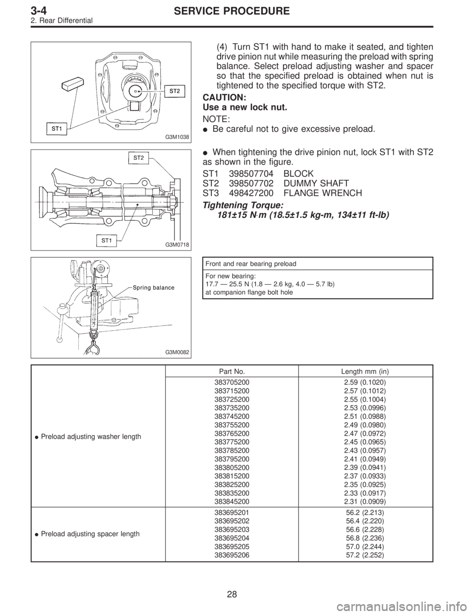
(4) Turn ST1 with hand to make it seated, and tighten
drive pinion nut while measuring the preload with spring
balance. Select preload adjusting washer and spacer
so that the specified preload is obtained when nut is
tightened to the specified torque with ST2.
CAUTION:
Use a new lock nut.
NOTE:
�Be careful not to give excessive preload.
G3M0718
�When tightening the drive pinion nut, lock ST1 with ST2
as shown in the figure.
ST1 398507704 BLOCK
ST2 398507702 DUMMY SHAFT
ST3 498427200 FLANGE WRENCH
Tightening Torque:
181±15 N⋅m (18.5±1.5 kg-m, 134±11 ft-lb)
G3M0082
Front and rear bearing preload
For new bearing:
17.7—25.5 N (1.8—2.6 kg, 4.0—5.7 lb)
at companion flange bolt hole
�Preload adjusting washer lengthPart No. Length mm (in)
383705200
383715200
383725200
383735200
383745200
383755200
383765200
383775200
383785200
383795200
383805200
383815200
383825200
383835200
3838452002.59 (0.1020)
2.57 (0.1012)
2.55 (0.1004)
2.53 (0.0996)
2.51 (0.0988)
2.49 (0.0980)
2.47 (0.0972)
2.45 (0.0965)
2.43 (0.0957)
2.41 (0.0949)
2.39 (0.0941)
2.37 (0.0933)
2.35 (0.0925)
2.33 (0.0917)
2.31 (0.0909)
�Preload adjusting spacer length383695201
383695202
383695203
383695204
383695205
38369520656.2 (2.213)
56.4 (2.220)
56.6 (2.228)
56.8 (2.236)
57.0 (2.244)
57.2 (2.252)
28
3-4SERVICE PROCEDURE
2. Rear Differential
Page 1069 of 3342
G3M0720
9) Press-fit companion flange with ST1 and ST2.
CAUTION:
Be careful not to damage bearing.
ST1 899874100 INSTALLER
ST2 399780104 WEIGHT
G3M1052
10) Install self-locking nut. Then tighten it with ST.
ST 498427200 FLANGE WRENCH
Tightening torque:
181±15 N⋅m (18.5±1.5 kg-m, 134±11 ft-lb)
G3M0069
11) Install crown gear on differential case.
Tightening Torque:
103±10 N⋅m (10.5±1.0 kg-m, 76±7 ft-lb)
NOTE:
Tighten diagonally while tapping the bolt heads.
G3M1041
12) Before installing side bearing, measure the bearing
width by using a dial gauge, ST1 and ST2.
Standard bearing width:
20.00 mm (0.7874 in)
NOTE:
Set the dial gauge needle to zero, using a standard bear-
ing or block of specified height in advance.
ST1 398227700 WEIGHT
ST2 398237700 GAUGE
G3M0091
13) Press side bearing cone onto differential case with
ST1.
ST1 398487700 DRIFT
31
3-4SERVICE PROCEDURE
2. Rear Differential
Page 1072 of 3342
G3M1035
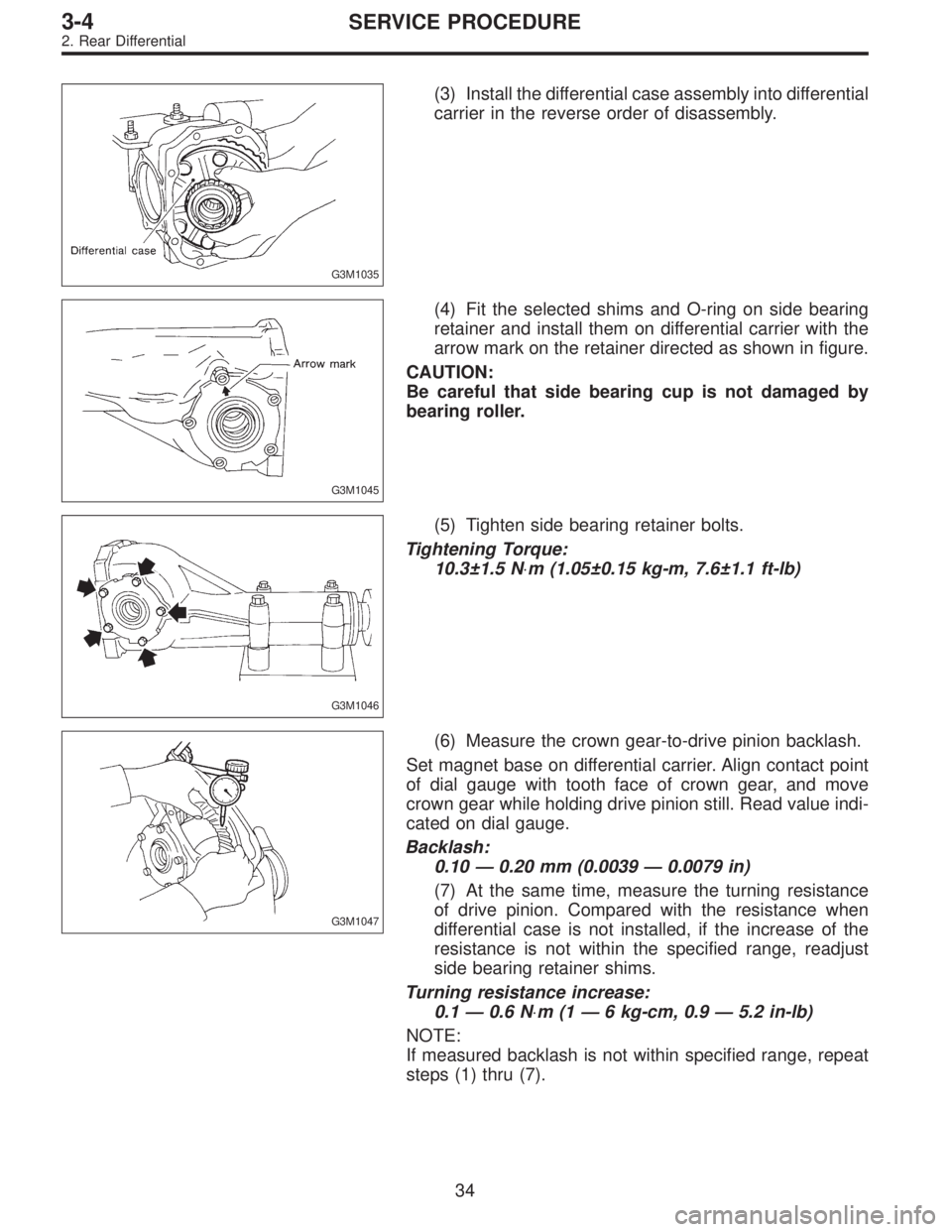
(3) Install the differential case assembly into differential
carrier in the reverse order of disassembly.
G3M1045
(4) Fit the selected shims and O-ring on side bearing
retainer and install them on differential carrier with the
arrow mark on the retainer directed as shown in figure.
CAUTION:
Be careful that side bearing cup is not damaged by
bearing roller.
G3M1046
(5) Tighten side bearing retainer bolts.
Tightening Torque:
10.3±1.5 N⋅m (1.05±0.15 kg-m, 7.6±1.1 ft-lb)
G3M1047
(6) Measure the crown gear-to-drive pinion backlash.
Set magnet base on differential carrier. Align contact point
of dial gauge with tooth face of crown gear, and move
crown gear while holding drive pinion still. Read value indi-
cated on dial gauge.
Backlash:
0.10 — 0.20 mm (0.0039 — 0.0079 in)
(7) At the same time, measure the turning resistance
of drive pinion. Compared with the resistance when
differential case is not installed, if the increase of the
resistance is not within the specified range, readjust
side bearing retainer shims.
Turning resistance increase:
0.1 — 0.6 N⋅m (1 — 6 kg-cm, 0.9 — 5.2 in-lb)
NOTE:
If measured backlash is not within specified range, repeat
steps (1) thru (7).
34
3-4SERVICE PROCEDURE
2. Rear Differential
Page 1075 of 3342
G3M1050
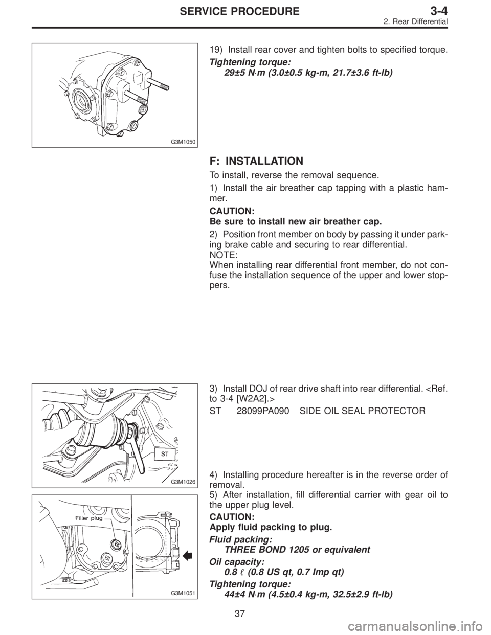
19) Install rear cover and tighten bolts to specified torque.
Tightening torque:
29±5 N⋅m (3.0±0.5 kg-m, 21.7±3.6 ft-lb)
F: INSTALLATION
To install, reverse the removal sequence.
1) Install the air breather cap tapping with a plastic ham-
mer.
CAUTION:
Be sure to install new air breather cap.
2) Position front member on body by passing it under park-
ing brake cable and securing to rear differential.
NOTE:
When installing rear differential front member, do not con-
fuse the installation sequence of the upper and lower stop-
pers.
G3M1026
3) Install DOJ of rear drive shaft into rear differential.
to 3-4 [W2A2].>
ST 28099PA090 SIDE OIL SEAL PROTECTOR
G3M1051
4) Installing procedure hereafter is in the reverse order of
removal.
5) After installation, fill differential carrier with gear oil to
the upper plug level.
CAUTION:
Apply fluid packing to plug.
Fluid packing:
THREE BOND 1205 or equivalent
Oil capacity:
0.8�(0.8 US qt, 0.7 Imp qt)
Tightening torque:
44±4 N⋅m (4.5±0.4 kg-m, 32.5±2.9 ft-lb)
37
3-4SERVICE PROCEDURE
2. Rear Differential
Page 1078 of 3342
1. Rear Differential
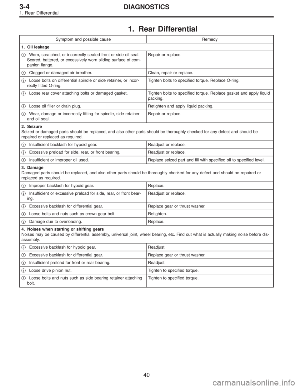
Symptom and possible cause Remedy
1. Oil leakage
�
1Worn, scratched, or incorrectly seated front or side oil seal.
Scored, battered, or excessively worn sliding surface of com-
panion flange.Repair or replace.
�
2Clogged or damaged air breather. Clean, repair or replace.
�
3Loose bolts on differential spindle or side retainer, or incor-
rectly fitted O-ring.Tighten bolts to specified torque. Replace O-ring.
�
4Loose rear cover attaching bolts or damaged gasket. Tighten bolts to specified torque. Replace gasket and apply liquid
packing.
�
5Loose oil filler or drain plug. Retighten and apply liquid packing.
�
6Wear, damage or incorrectly fitting for spindle, side retainer
and oil seal.Repair or replace.
2. Seizure
Seized or damaged parts should be replaced, and also other parts should be thoroughly checked for any defect and should be
repaired or replaced as required.
�
1Insufficient backlash for hypoid gear. Readjust or replace.
�
2Excessive preload for side, rear, or front bearing. Readjust or replace.
�
3Insufficient or improper oil used. Replace seized part and fill with specified oil to specified level.
3. Damage
Damaged parts should be replaced, and also other parts should be thoroughly checked for any defect and should be repaired or
replaced as required.
�
1Improper backlash for hypoid gear. Replace.
�
2Insufficient or excessive preload for side, rear, or front bear-
ing.Readjust or replace.
�
3Excessive backlash for differential gear. Replace gear or thrust washer.
�
4Loose bolts and nuts such as crown gear bolt. Retighten.
�
5Damage due to overloading. Replace.
4. Noises when starting or shifting gears
Noises may be caused by differential assembly, universal joint, wheel bearing, etc. Find out what is actually making noise before dis-
assembly.
�
1Excessive backlash for hypoid gear. Readjust.
�
2Excessive backlash for differential gear. Replace gear or thrust washer.
�
3Insufficient preload for front or rear bearing. Readjust.
�
4Loose drive pinion nut. Tighten to specified torque.
�
5Loose bolts and nuts such as side bearing retainer attaching
bolt.Tighten to specified torque.
40
3-4DIAGNOSTICS
1. Rear Differential
Page 1083 of 3342
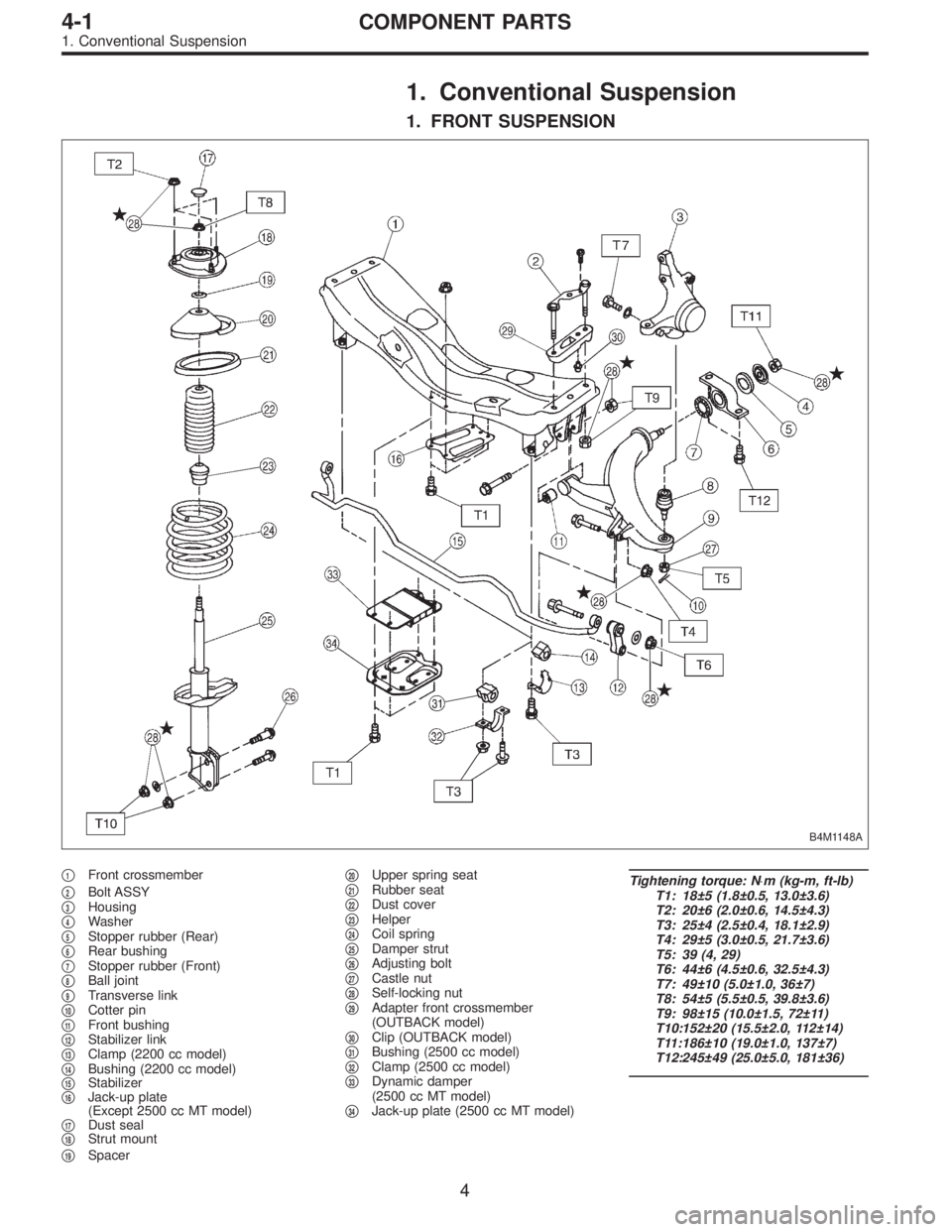
1. Conventional Suspension
1. FRONT SUSPENSION
B4M1148A
�1Front crossmember
�
2Bolt ASSY
�3Housing
�4Washer
�5Stopper rubber (Rear)
�6Rear bushing
�7Stopper rubber (Front)
�8Ball joint
�9Transverse link
�10Cotter pin
�11Front bushing
�12Stabilizer link
�13Clamp (2200 cc model)
�14Bushing (2200 cc model)
�15Stabilizer
�16Jack-up plate
(Except 2500 cc MT model)
�
17Dust seal
�18Strut mount
�
19Spacer�
20Upper spring seat
�21Rubber seat
�22Dust cover
�23Helper
�24Coil spring
�25Damper strut
�26Adjusting bolt
�27Castle nut
�28Self-locking nut
�29Adapter front crossmember
(OUTBACK model)
�
30Clip (OUTBACK model)
�31Bushing (2500 cc model)
�32Clamp (2500 cc model)
�33Dynamic damper
(2500 cc MT model)
�
34Jack-up plate (2500 cc MT model)
Tightening torque: N⋅m (kg-m, ft-lb)
T1: 18±5 (1.8±0.5, 13.0±3.6)
T2: 20±6 (2.0±0.6, 14.5±4.3)
T3: 25±4 (2.5±0.4, 18.1±2.9)
T4: 29±5 (3.0±0.5, 21.7±3.6)
T5: 39 (4, 29)
T6: 44±6 (4.5±0.6, 32.5±4.3)
T7: 49±10 (5.0±1.0, 36±7)
T8: 54±5 (5.5±0.5, 39.8±3.6)
T9: 98±15 (10.0±1.5, 72±11)
T10:152±20 (15.5±2.0, 112±14)
T11:186±10 (19.0±1.0, 137±7)
T12:245±49 (25.0±5.0, 181±36)
4
4-1COMPONENT PARTS
1. Conventional Suspension