Page 1131 of 3342
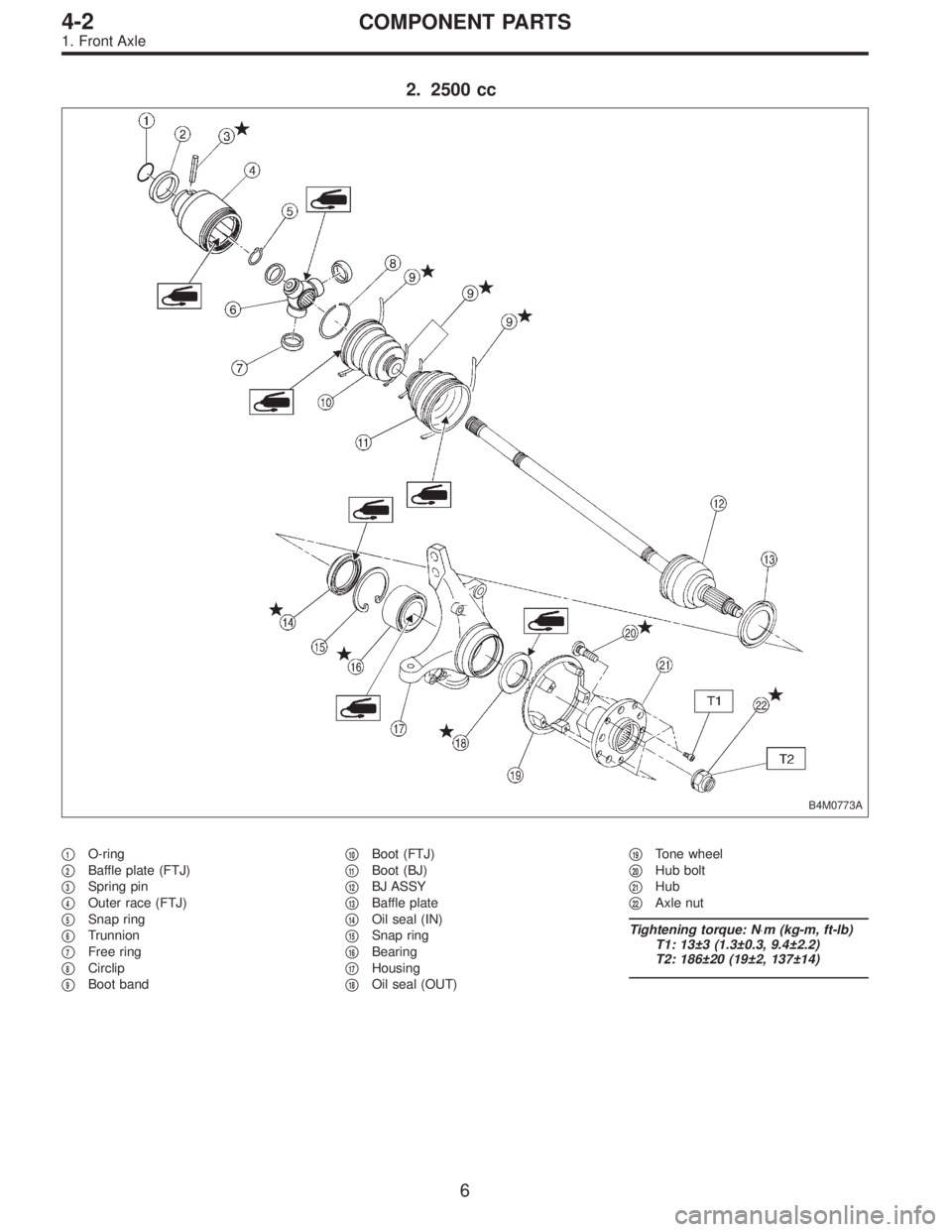
2. 2500 cc
B4M0773A
�1O-ring
�
2Baffle plate (FTJ)
�
3Spring pin
�
4Outer race (FTJ)
�
5Snap ring
�
6Trunnion
�
7Free ring
�
8Circlip
�
9Boot band�
10Boot (FTJ)
�
11Boot (BJ)
�
12BJ ASSY
�
13Baffle plate
�
14Oil seal (IN)
�
15Snap ring
�
16Bearing
�
17Housing
�
18Oil seal (OUT)�
19Tone wheel
�
20Hub bolt
�
21Hub
�
22Axle nut
Tightening torque: N⋅m (kg-m, ft-lb)
T1: 13±3 (1.3±0.3, 9.4±2.2)
T2: 186±20 (19±2, 137±14)
6
4-2COMPONENT PARTS
1. Front Axle
Page 1132 of 3342
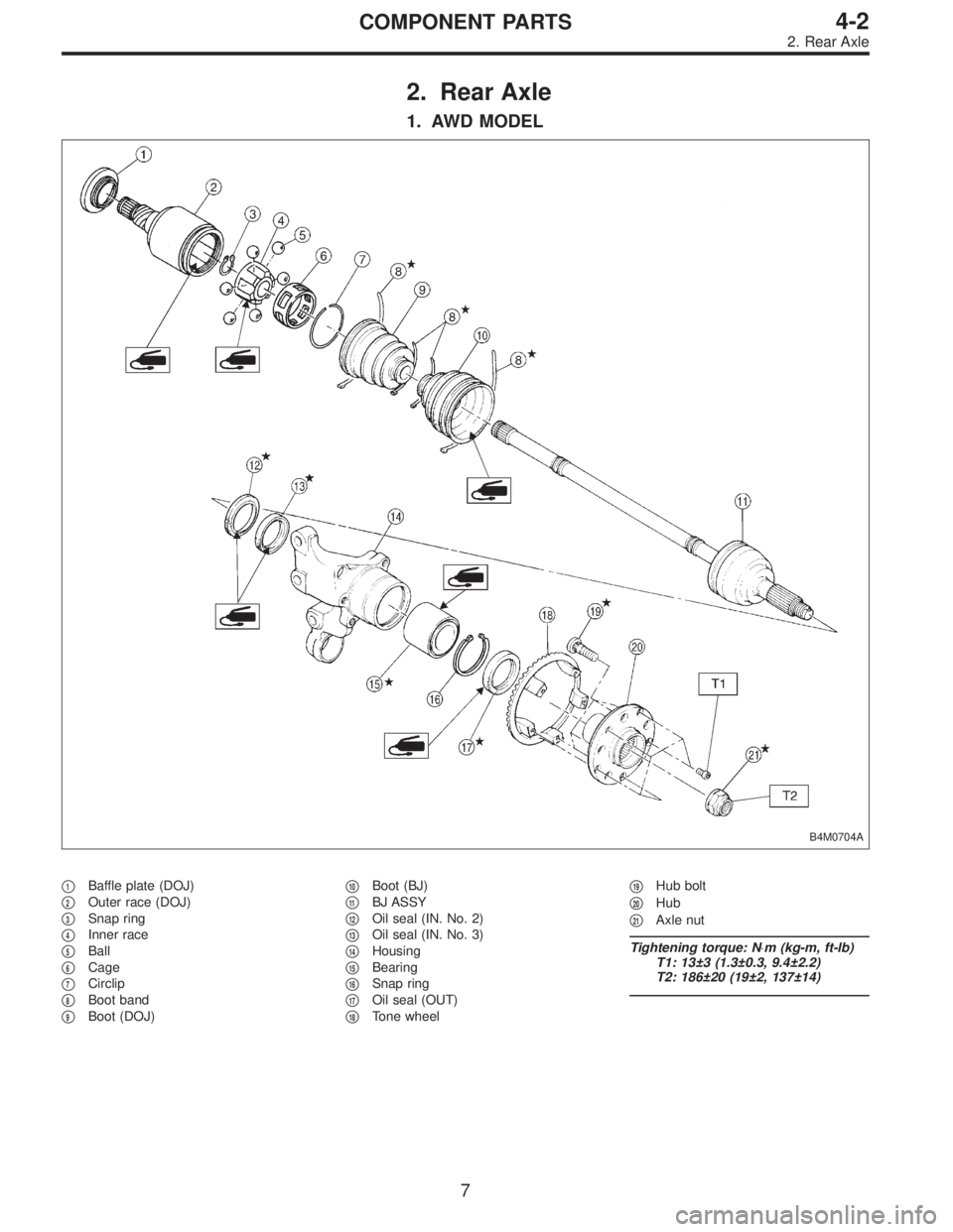
2. Rear Axle
1. AWD MODEL
B4M0704A
�1Baffle plate (DOJ)
�
2Outer race (DOJ)
�
3Snap ring
�
4Inner race
�
5Ball
�
6Cage
�
7Circlip
�
8Boot band
�
9Boot (DOJ)�
10Boot (BJ)
�
11BJ ASSY
�
12Oil seal (IN. No. 2)
�
13Oil seal (IN. No. 3)
�
14Housing
�
15Bearing
�
16Snap ring
�
17Oil seal (OUT)
�
18Tone wheel�
19Hub bolt
�
20Hub
�
21Axle nut
Tightening torque: N⋅m (kg-m, ft-lb)
T1: 13±3 (1.3±0.3, 9.4±2.2)
T2: 186±20 (19±2, 137±14)
7
4-2COMPONENT PARTS
2. Rear Axle
Page 1133 of 3342
2. FWD MODEL
G4M0213
�1Hub cap
�
2O-ring
�
3Axle nut
�
4Washer�
5Hub unit
�
6SpindleTightening torque: N⋅m (kg-m, ft-lb)
T: 186±20 (19±2, 137±14)
8
4-2COMPONENT PARTS
2. Rear Axle
Page 1139 of 3342
G4M0233
7) Using ST1 and ST2, press outer oil seal until it contacts
the bottom of housing.
ST1 927410000 OIL SEAL INSTALLER
ST2 927400000 HOUSING STAND
G4M0234
8) Using ST1 and ST2, press inner oil seal until it contacts
circlip.
ST1 927410000 OIL SEAL INSTALLER
ST2 927400000 HOUSING STAND
9) Invert ST and housing.
ST 927400000 HOUSING STAND
10) Apply sufficient grease to oil seal lip.
Specified grease:
SHELL 6459N
CAUTION:
�If specified grease is not available, remove bearing
grease and apply Auto Rex A instead.
�Do not mix different types of grease.
11) Install disc cover to housing the three bolts.
Tightening torque:
14±4 N⋅m (1.4±0.4 kg-m, 10.1±2.9 ft-lb)
G4M0235
12) Attach hub to ST1 securely.
13) Clean dust or foreign particles from the polished sur-
face of hub.
14) Using ST2, press bearing into hub by driving inner
race.
ST1 927080000 HUB STAND
ST2 927120000 HUB INSTALLER
14
4-2SERVICE PROCEDURE
1. Front Axle
Page 1140 of 3342
 Install transverse link ball joint to housing.
Tightening torque:
44±6 N⋅m (4.5±0.6 kg-m, 32.5±4.3 ft-lb)
2) While aligning alignment mark on camber adjusting bolt
head, connec")
E: INSTALLATION
1) Install transverse link ball joint to housing.
Tightening torque:
44±6 N⋅m (4.5±0.6 kg-m, 32.5±4.3 ft-lb)
2) While aligning alignment mark on camber adjusting bolt
head, connect housing and strut.
CAUTION:
Use a new self-locking nut.
Tightening torque:
147±15 N⋅m (15±1.5 kg-m, 108±11 ft-lb)
3) Install speed sensor and harness on housing (only
vehicle equipped with A.B.S.).
4) Install disc rotor on hub.
5) Install disc brake caliper on housing.
Tightening torque:
59±10 N⋅m (6±1 kg-m, 43±7 ft-lb)
6) Install front drive shaft.
7) Connect stabilizer link.
G4M0236
8) Install tie-rod end ball joint on housing knuckle arm.
Tightening torque:
27.0±2.5 N⋅m (2.75±0.25 kg-m, 19.9±1.8 ft-lb)
G4M0237
9) While depressing brake pedal, tighten axle nut and lock
it securely.
Tightening torque:
186±20 N⋅m (19±2 kg-m, 137±14 ft-lb)
CAUTION:
�Use a new axle nut.
�Always tighten axle nut before installing wheel on
vehicle. If wheel is installed and comes in contact with
ground when axle nut is loose, wheel bearings may be
damaged.
�Be sure to tighten axle nut to specified torque. Do
not overtighten it as this may damage wheel bearing.
15
4-2SERVICE PROCEDURE
1. Front Axle
Page 1141 of 3342
G4M0238
10) After tightening axle nut, lock it securely.
11) Install wheel and tighten wheel nuts to specified
torque.
Tightening torque:
88±10 N⋅m (9±1 kg-m, 65±7 ft-lb)
2. Rear Axle (AWD Model)
A: REMOVAL
1) Disconnect ground cable from battery.
2) Jack-up vehicle, and remove rear wheel cap and
wheels.
CAUTION:
Be sure to loosen and retighten axle nut after remov-
ing wheel from vehicle. Failure to follow this rule may
damage wheel bearings.
3) Unlock axle nut.
4) Remove axle nut using a socket wrench.
B4M0050A
5) Return parking brake lever and loosen adjusting nut.
(1) Disc brake: Perform steps 6) and 7).
(2) Drum brake: Perform steps 8) through 10).
G4M0240
6) Remove disc brake caliper from back plate, and sus-
pend it from strut using a piece of wire.
7) Remove disc rotor from hub.
NOTE:
If disc rotor seizes up within hub, drive it out by installing
an 8-mm bolt into bolt hole in disc rotor.
16
4-2SERVICE PROCEDURE
1. Front Axle - 2. Rear Axle (AWD Model)
Page 1142 of 3342
G4M0238
10) After tightening axle nut, lock it securely.
11) Install wheel and tighten wheel nuts to specified
torque.
Tightening torque:
88±10 N⋅m (9±1 kg-m, 65±7 ft-lb)
2. Rear Axle (AWD Model)
A: REMOVAL
1) Disconnect ground cable from battery.
2) Jack-up vehicle, and remove rear wheel cap and
wheels.
CAUTION:
Be sure to loosen and retighten axle nut after remov-
ing wheel from vehicle. Failure to follow this rule may
damage wheel bearings.
3) Unlock axle nut.
4) Remove axle nut using a socket wrench.
B4M0050A
5) Return parking brake lever and loosen adjusting nut.
(1) Disc brake: Perform steps 6) and 7).
(2) Drum brake: Perform steps 8) through 10).
G4M0240
6) Remove disc brake caliper from back plate, and sus-
pend it from strut using a piece of wire.
7) Remove disc rotor from hub.
NOTE:
If disc rotor seizes up within hub, drive it out by installing
an 8-mm bolt into bolt hole in disc rotor.
16
4-2SERVICE PROCEDURE
1. Front Axle - 2. Rear Axle (AWD Model)
Page 1147 of 3342
G4M0259
6) Invert both ST1 and housing.
7) Using ST2, press inner oil seal into housing until it
touches bottom.
ST1 927430000 HOUSING STAND
ST2 927460000 OIL SEAL INSTALLER
G4M0260
8) Using ST1 and ST2, press sub seal into place.
ST1 927430000 HOUSING STAND
ST2 927460000 OIL SEAL INSTALLER
9) Apply sufficient grease to oil seal lip.
Specified grease:
SHELL 6459N
CAUTION:
�If specified grease is not available, remove bearing
grease and apply Auto Rex A instead.
�Do not mix different types of grease.
G4M0261
10) Install back plate to rear housing.
Tightening torque:
52±6 N⋅m (5.3±0.6 kg-m, 38.3±4.3 ft-lb)
G4M0262
11) Using ST1 and ST2, press bearing into hub.
ST1 927080000 HUB STAND
ST2 927450000 HUB INSTALLER
21
4-2SERVICE PROCEDURE
2. Rear Axle (AWD Model)
 Using ST1 and ST2, press outer oil seal until it contacts
the bottom of housing.
ST1 927410000 OIL SEAL INSTALLER
ST2 927400000 HOUSING STAND
G4M0234
8) Using ST1 and ST2, press inner oil s")
 After tightening axle nut, lock it securely.
11) Install wheel and tighten wheel nuts to specified
torque.
Tightening torque:
88±10 N⋅m (9±1 kg-m, 65±7 ft-lb)
2. Rear Axle (AWD Model)")
 After tightening axle nut, lock it securely.
11) Install wheel and tighten wheel nuts to specified
torque.
Tightening torque:
88±10 N⋅m (9±1 kg-m, 65±7 ft-lb)
2. Rear Axle (AWD Model)")
 Invert both ST1 and housing.
7) Using ST2, press inner oil seal into housing until it
touches bottom.
ST1 927430000 HOUSING STAND
ST2 927460000 OIL SEAL INSTALLER
G4M0260
8) Using ST1 and S")