Page 1084 of 3342

B4M0766A
�1Stabilizer
�
2Stabilizer bracket
�
3Stabilizer bushing
�
4Clamp
�
5Floating bushing
�
6Stopper
�
7Stabilizer link
�
8Rear lateral link
�
9Bushing (C)
�
10Bush")
2. REAR SUSPENSION (AWD MODEL)
B4M0766A
�1Stabilizer
�
2Stabilizer bracket
�
3Stabilizer bushing
�
4Clamp
�
5Floating bushing
�
6Stopper
�
7Stabilizer link
�
8Rear lateral link
�
9Bushing (C)
�
10Bushing (A)
�
11Front lateral link
�
12Bushing (B)
�
13Trailing link rear bushing
�
14Trailing link
�
15Trailing link front bushing�
16Trailing link bracket
�
17Cap (Protection)
�
18Washer
�
19Rear crossmember
�
20Strut mount cap
�
21Strut mount
�
22Rubber seat upper
�
23Dust cover
�
24Coil spring
�
25Helper
�
26Rubber seat lower
�
27Damper strut
�
28Self-locking nut
�
29Crossmember reinforcement
lower (Sedan model)
�
30Adapter rear crossmember (OUT-
BACK model)
Tightening torque: N⋅m (kg-m, ft-lb)
T1: 20±6 (2.0±0.6, 14.5±4.3)
T2: 25±7 (2.5±0.7, 18.1±5.1)
T3: 44±6 (4.5±0.6, 32.5±4.3)
T4: 59±10 (6.0±1.0, 43±7)
T5: 98±15 (10.0±1.5, 72±11)
T6: 98±20 (10.0±2.0, 72±14)
T7: 113±15 (11.5±1.5, 83±11)
T8: 127±20 (13.0±2.0, 94±14)
T9: 137±20 (14.0±2.0, 101±14)
T10:196
+39
�10(20.0+4.0
�1.0, 145+29
�7)
5
4-1COMPONENT PARTS
1. Conventional Suspension
Page 1085 of 3342
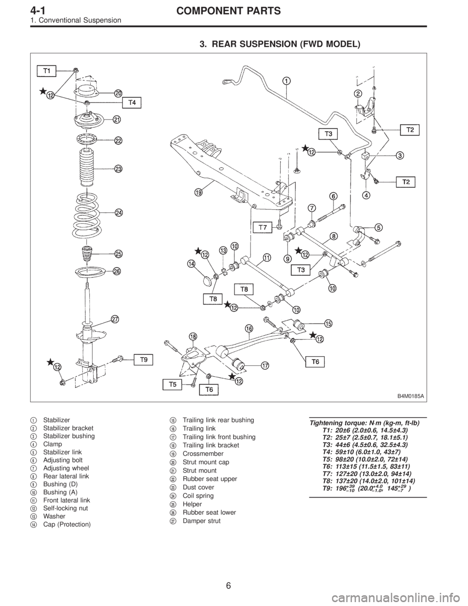
3. REAR SUSPENSION (FWD MODEL)
B4M0185A
�1Stabilizer
�
2Stabilizer bracket
�
3Stabilizer bushing
�
4Clamp
�
5Stabilizer link
�
6Adjusting bolt
�
7Adjusting wheel
�
8Rear lateral link
�
9Bushing (D)
�
10Bushing (A)
�
11Front lateral link
�
12Self-locking nut
�
13Washer
�
14Cap (Protection)�
15Trailing link rear bushing
�
16Trailing link
�
17Trailing link front bushing
�
18Trailing link bracket
�
19Crossmember
�
20Strut mount cap
�
21Strut mount
�
22Rubber seat upper
�
23Dust cover
�
24Coil spring
�
25Helper
�
26Rubber seat lower
�
27Damper strut
Tightening torque: N⋅m (kg-m, ft-lb)
T1: 20±6 (2.0±0.6, 14.5±4.3)
T2: 25±7 (2.5±0.7, 18.1±5.1)
T3: 44±6 (4.5±0.6, 32.5±4.3)
T4: 59±10 (6.0±1.0, 43±7)
T5: 98±20 (10.0±2.0, 72±14)
T6: 113±15 (11.5±1.5, 83±11)
T7: 127±20 (13.0±2.0, 94±14)
T8: 137±20 (14.0±2.0, 101±14)
T9: 196
+39
�10(20.0+4.0
�1.0, 145+29
�7)
6
4-1COMPONENT PARTS
1. Conventional Suspension
Page 1089 of 3342
Left side Right side
Camber is increased.
B4M0190
Rotate
counterclockwise.
B4M0350
Rotate clockwise.
Camber is decreased.
B4M0350
Rotate clockwise.
B4M0190
Rotate
counterclockwise.
3) Tighten the two self-locking nuts.
Tightening torque:
152±20 N⋅m (15.5±2.0 kg-m, 112±14 ft-lb)
M4A0059
3. FRONT WHEEL TOE-IN
�Inspection
1) Using a toe gauge, measure front wheel toe-in.
Toe-in: 0±3 mm (0±0.12 in)
2) Mark rear sides of left and right tires at height corre-
sponding to center of spindles and measure distance“B”
between marks.
3) Move vehicle forward so that marks line up with front
sides at height corresponding to center of spindles.
4) Measure distance“A”between left and right marks.
Toe-in can then be obtained by the following equation:
B�A = Toe-in
10
4-1SERVICE PROCEDURE
1. On-car Services
Page 1090 of 3342
 Loosen the left and right side steering tie-rods lock nuts.
2) Turn the left and right tie rods equal amounts until the
toe-in is at the specification.
Both the left and right t")
G4M0482
�Adjustment
1) Loosen the left and right side steering tie-rods lock nuts.
2) Turn the left and right tie rods equal amounts until the
toe-in is at the specification.
Both the left and right tie-rods are right-hand threaded. To
increase toe-in, turn both tie-rods clockwise equal amounts
(as viewed from the inside of the vehicle).
3) Tighten tie-rod lock nut.
Tightening torque:
83±5 N⋅m (8.5±0.5 kg-m, 61.5±3.6 ft-lb)
CAUTION:
Correct tie-rod boot, if it is twisted.
NOTE:
Check the left and right wheel steering angle is within
specifications.
M4A0059
4. REAR WHEEL TOE-IN (FWD MODEL)
�Inspection
1) Using a toe-in gauge, measure rear wheel toe-in.
Toe-in: 0±3 mm (0±0.12 in)
2) Mark rear sides of left and right tires at height corre-
sponding to center of spindles and measure distance“B”
between marks.
3) Move vehicle forward so that marks line up with front
sides at height corresponding to center of spindles.
4) Measure distance“A”between left and right marks.
Toe-in can then be obtained by the following equation:
B�A = Toe-in
G4M0483
�Adjustment
1) Remove cap from lateral link and loosen self-locking
nut.
CAUTION:
�When loosening or tightening adjusting bolt, hold
the bolt head and loosen self-locking nut.
�Replace self-locking nut with a new one.
2) Using two wrenches, turn adjusting wheel and adjusting
bolt equally in opposite directions so that toe-in is at the
specification.
11
4-1SERVICE PROCEDURE
1. On-car Services
Page 1091 of 3342

Left side Right side
Toe-in is
increased.
B4M0191A
Turn adjusting
wheel
counterclockwise
and adjusting bolt
clockwise.
B4M0351A
Turn adjusting
wheel clockwise
and adjusting bolt
counterclockwise.
Toe-in is
decreased.
B4M0351A
Turn adjusting
wheel clockwise
and adjusting bolt
counterclockwise.
B4M0191A
Turn adjusting
wheel
counterclockwise
and adjusting bolt
clockwise.
G4M0485
NOTE:
�When left and right wheels are adjusted for toe-in at the
same time, moving one scale graduation changes toe-in by
approximately 4 mm (0.16 in).
�Turn adjusting wheel and adjusting bolt equally in oppo-
site directions so that same scale graduations are posi-
tioned directly above center of the adjusting bolt.
3) Tighten self-locking nut.
Tightening torque:
137±20 N⋅m (14±2 kg-m, 101±14 ft-lb)
M4A0059
5. REAR WHEEL TOE-IN (AWD MODEL)
�Inspection
1) Using a toe-in gauge, measure rear wheel toe-in.
Toe-in: 0±3 mm (0±0.12 in)
2) Mark rear sides of left and right tires at height corre-
sponding to center of spindles and measure distance“B”
between marks.
3) Move vehicle forward so that marks line up with front
sides at height corresponding to center of spindles.
4) Measure distance“A”between left and right marks.
Toe-in can then be obtained by the following equation:
B�A = Toe-in
12
4-1SERVICE PROCEDURE
1. On-car Services
Page 1092 of 3342
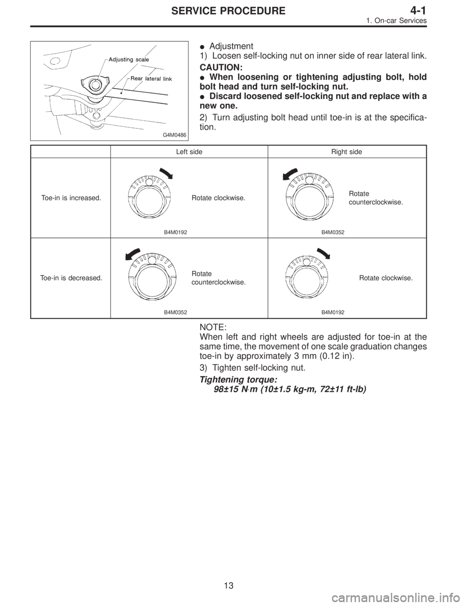
G4M0486
�Adjustment
1) Loosen self-locking nut on inner side of rear lateral link.
CAUTION:
�When loosening or tightening adjusting bolt, hold
bolt head and turn self-locking nut.
�Discard loosened self-locking nut and replace with a
new one.
2) Turn adjusting bolt head until toe-in is at the specifica-
tion.
Left side Right side
Toe-in is increased.
B4M0192
Rotate clockwise.
B4M0352
Rotate
counterclockwise.
Toe-in is decreased.
B4M0352
Rotate
counterclockwise.
B4M0192
Rotate clockwise.
NOTE:
When left and right wheels are adjusted for toe-in at the
same time, the movement of one scale graduation changes
toe-in by approximately 3 mm (0.12 in).
3) Tighten self-locking nut.
Tightening torque:
98±15 N⋅m (10±1.5 kg-m, 72±11 ft-lb)
13
4-1SERVICE PROCEDURE
1. On-car Services
Page 1095 of 3342
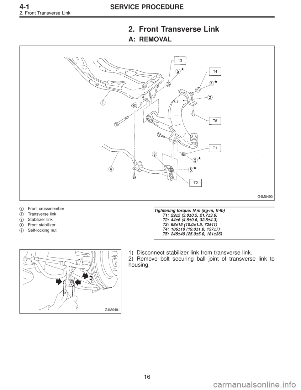
2. Front Transverse Link
A: REMOVAL
G4M0490
�1Front crossmember
�
2Transverse link
�
3Stabilizer link
�
4Front stabilizer
�
5Self-locking nut
Tightening torque: N⋅m (kg-m, ft-lb)
T1: 29±5 (3.0±0.5, 21.7±3.6)
T2: 44±6 (4.5±0.6, 32.5±4.3)
T3: 98±15 (10.0±1.5, 72±11)
T4: 186±10 (19.0±1.0, 137±7)
T5: 245±49 (25.0±5.0, 181±36)
G4M0491
1) Disconnect stabilizer link from transverse link.
2) Remove bolt securing ball joint of transverse link to
housing.
16
4-1SERVICE PROCEDURE
2. Front Transverse Link
Page 1097 of 3342
 Install rear bushing to")
G4M0496
D: ASSEMBLY
1. FRONT BUSHING
To reassemble, reverse disassembly procedures.
CAUTION:
Install front bushing in correct direction, as shown in
figure.
2. REAR BUSHING
1) Install rear bushing to transverse link and align aligning
marks scribed on the two.
2) Tighten self-locking nut.
CAUTION:
�Discard loosened self-locking nut and replace with a
new one.
�While holding rear bushing so as not to change
position of aligning marks, tighten self-locking nut.
Tightening torque:
186±10 N⋅m (19.0±1.0 kg-m, 137±7 ft-lb)
E: INSTALLATION
1) Temporarily tighten the two bolts used to secure rear
bushing of the transverse link to body.
NOTE:
These bolts should be tightened to such an extent that they
can still move back and forth in the oblong shaped hole in
the bracket (which holds the bushing).
2) Install bolts used to connect transverse link to cross-
member and temporarily tighten with nut.
CAUTION:
Discard loosened self-locking nut and replace with a
new one.
3) Insert ball joint into housing.
18
4-1SERVICE PROCEDURE
2. Front Transverse Link
 Tighten the two")