Page 1033 of 3342
B3M0010
E: INSTALLATION
1) Put into gearshift lever from passenger compartment.
2) Mount boot plate on the body.
3) Install console box and gearshift knob.
[W1B0].>
G3M0684
4) Mount cushion rubber on the body.
Tightening torque:
18±5 N⋅m (1.84±0.51 kg-m, 13.3±3.7 ft-lb)
B3M0616A
5) Connect rod to the joint.
Tightening torque:
FWD model
12±3 N⋅m (1.2±0.3 kg-m, 8.7±2.2 ft-lb)
AWD model
18±5 N⋅m (1.84±0.51 kg-m, 13.3±3.7 ft-lb)
G3M0681
6) Connect stay to the bracket.
Tightening torque:
18±5 N⋅m (1.84±0.51 kg-m, 13.3±3.7 ft-lb)
7) Install the exhaust cover.
10
3-3SERVICE PROCEDURE
1. Manual Transmission
Page 1036 of 3342
 Remove detention spring.
C: INSPECTION
1) Inspect removed parts by comparing with new ones for
deformation, damage and wear. Correct or replace if defec-
tive.
2) Confirm the following part")
G3M0709
8) Remove detention spring.
C: INSPECTION
1) Inspect removed parts by comparing with new ones for
deformation, damage and wear. Correct or replace if defec-
tive.
2) Confirm the following parts for operating condition
before assembly.
(1) Sliding condition of the button in the grip ... it should
move smoothly.
(2) Insertion of the grip on the selector lever ... when
pushing the grip on the selector lever by hand, screw
holes should be aligned.
(3) Operation of selector lever and rod ... they should
move smoothly.
(4) Insertion of the spacer into the selector lever ... it
should be inserted lightly by finger pressure.
G3M0707
D: ASSEMBLY
1) Clean all parts before assembly.
Apply grease [NIGLUBE-R or equivalent].
2) Assemble selector lever to the plate.
3) Insert the bolt and tighten the flange nut to the specified
torque.
Tightening torque (Flange nut):
12±3 N⋅m (1.2±0.3 kg-m, 8.7±2.2 ft-lb)
G3M0710
4) Assemble detention spring, shift-lock solenoid and“P”
position switch.
13
3-3SERVICE PROCEDURE
2. Automatic Transmission
Page 1037 of 3342
G3M0711
5) Adjust the position of shift-lock plate and solenoid.
Then, tighten bolts.
G3M0712
6) Assemble indicator to the plate
Tightening torque:
4.4±1.5 N⋅m (0.45±0.15 kg-m, 3.3±1.1 ft-lb)
B3M0347A
7) Assemble the following parts to the grip.
CAUTION:
Apply grease on sliding surfaces of the following
parts.
�
1Button
�
2Spring
G3M0714
8) Assemble the grip to the selector lever.
9) After completion of fitting, transfer selector lever to
range“P”∼“1”, pressing the button of the grip; then check
whether the indicator and select lever agree, whether the
pointer and position mark agree and what the operating
force is.
14
3-3SERVICE PROCEDURE
2. Automatic Transmission
Page 1038 of 3342
 Mount the selector lever onto the vehicle body.
2) Tighten the six bolts to install the selector lever to the
vehicle body.
Tightening torque:
4.5±1.5 N⋅m (0.45±0.15 kg-")
G3M0703
E: INSTALLATION
1) Mount the selector lever onto the vehicle body.
2) Tighten the six bolts to install the selector lever to the
vehicle body.
Tightening torque:
4.5±1.5 N⋅m (0.45±0.15 kg-m, 3.3±1.1 ft-lb)
G3M0702
3) Connect connectors and install rear console, center
console and instrument console.
G3M0715
4) Set location of selector lever at“N”position.
5) Set location of selector arm installed on the transmis-
sion body at“N”position.
B3M0416A
6) Pass inner cable through selector arm pin and then
connect it using a washer and snap pin.
7) Attach outer cable to plate on transmission case with
the bolts.
Tightening torque:
18±5 N⋅m (1.8±0.5 kg-m, 13.0±3.6 ft-lb)
B3M0417A
8) Insert the thread portion of the other inner cable end
into the connector hole of the selector lever, and fix the
other outer cable end to the bracket.
9) Adjust the inner cable length.
(1) Put connector into contact with nut�
2.
(2) Tighten nut�
1.
Tightening torque:
7.4±2.0 N⋅m (0.75±0.2 kg-m, 5.4±1.4 ft-lb)
15
3-3SERVICE PROCEDURE
2. Automatic Transmission
Page 1044 of 3342
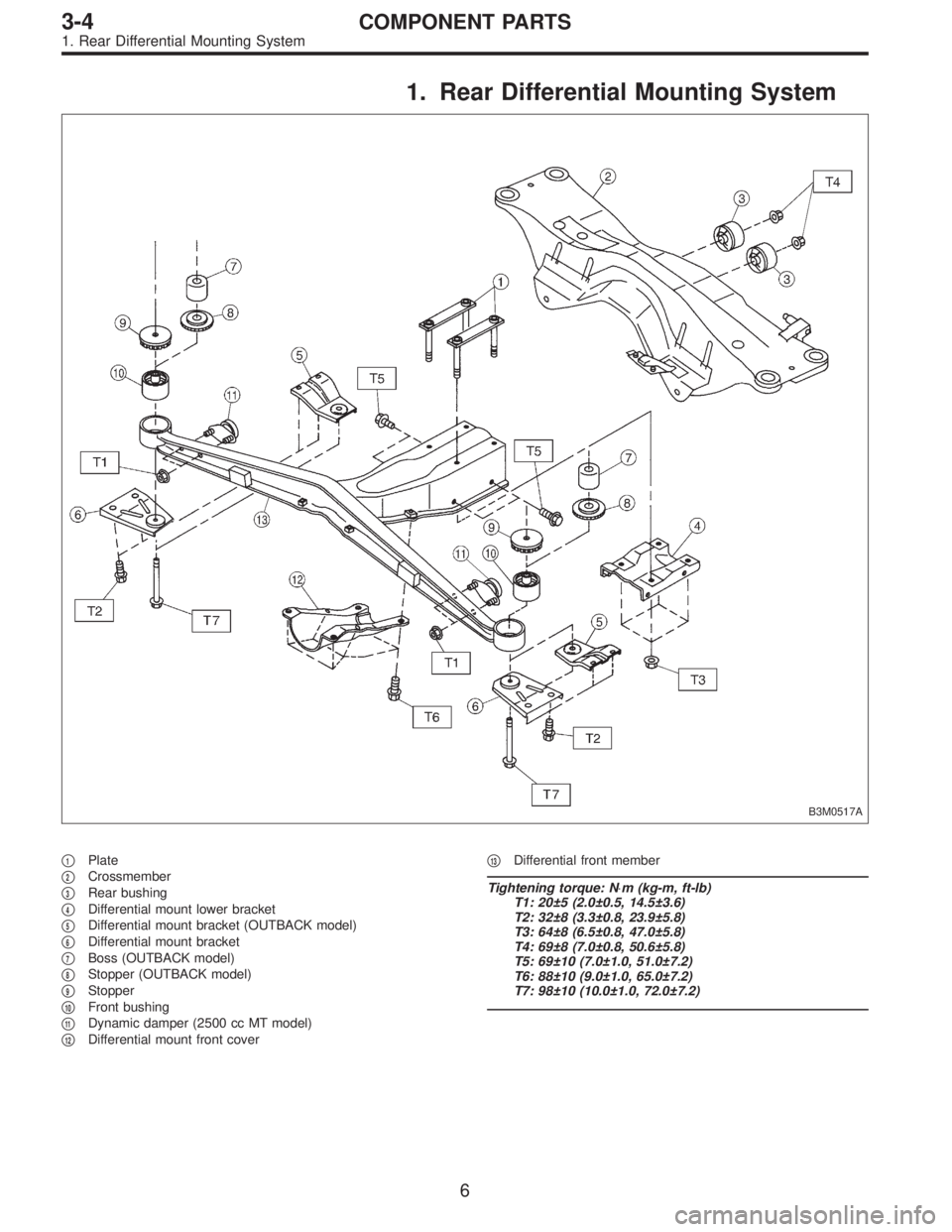
1. Rear Differential Mounting System
B3M0517A
�1Plate
�
2Crossmember
�
3Rear bushing
�
4Differential mount lower bracket
�
5Differential mount bracket (OUTBACK model)
�
6Differential mount bracket
�
7Boss (OUTBACK model)
�
8Stopper (OUTBACK model)
�
9Stopper
�
10Front bushing
�
11Dynamic damper (2500 cc MT model)
�
12Differential mount front cover�
13Differential front member
Tightening torque: N⋅m (kg-m, ft-lb)
T1: 20±5 (2.0±0.5, 14.5±3.6)
T2: 32±8 (3.3±0.8, 23.9±5.8)
T3: 64±8 (6.5±0.8, 47.0±5.8)
T4: 69±8 (7.0±0.8, 50.6±5.8)
T5: 69±10 (7.0±1.0, 51.0±7.2)
T6: 88±10 (9.0±1.0, 65.0±7.2)
T7: 98±10 (10.0±1.0, 72.0±7.2)
6
3-4COMPONENT PARTS
1. Rear Differential Mounting System
Page 1045 of 3342
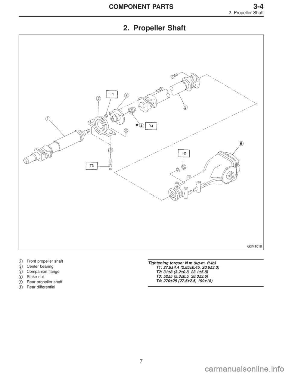
2. Propeller Shaft
G3M1018
�1Front propeller shaft
�
2Center bearing
�
3Companion flange
�
4Stake nut
�
5Rear propeller shaft
�
6Rear differential
Tightening torque: N⋅m (kg-m, ft-lb)
T1: 27.9±4.4 (2.85±0.45, 20.6±3.3)
T2: 31±8 (3.2±0.8, 23.1±5.8)
T3: 52±5 (5.3±0.5, 38.3±3.6)
T4: 270±25 (27.5±2.5, 199±18)
7
3-4COMPONENT PARTS
2. Propeller Shaft
Page 1046 of 3342
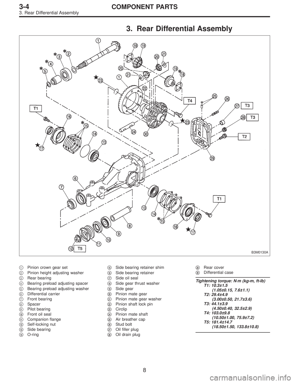
3. Rear Differential Assembly
B3M0130A
�1Pinion crown gear set
�
2Pinion height adjusting washer
�
3Rear bearing
�
4Bearing preload adjusting spacer
�
5Bearing preload adjusting washer
�
6Differential carrier
�
7Front bearing
�
8Spacer
�
9Pilot bearing
�
10Front oil seal
�
11Companion flange
�
12Self-locking nut
�
13Side bearing
�
14O-ring�
15Side bearing retainer shim
�
16Side bearing retainer
�
17Side oil seal
�
18Side gear thrust washer
�
19Side gear
�
20Pinion mate gear
�
21Pinion mate gear washer
�
22Pinion shaft lock pin
�
23Circlip
�
24Pinion mate shaft
�
25Air breather cap
�
26Stud bolt
�
27Oil filler plug
�
28Oil drain plug�
29Rear cover
�
30Differential case
Tightening torque: N⋅m (kg-m, ft-lb)
T1: 10.3±1.5
(1.05±0.15, 7.6±1.1)
T2: 29.4±4.9
(3.00±0.50, 21.7±3.6)
T3: 44.1±3.9
(4.50±0.40, 32.5±2.9)
T4: 103.0±9.8
(10.50±1.00, 75.9±7.2)
T5: 181.4±14.7
(18.50±1.50, 133.8±10.8)
8
3-4COMPONENT PARTS
3. Rear Differential Assembly
Page 1050 of 3342
G3M0031
5) Lightly tap the head of front propeller shaft with a cop-
per hammer until center bearing is removed.
CAUTION:
Be careful not to damage the thread portion.
D: INSPECTION
NOTE:
Do not disassemble propeller shaft. Check the following
and replace if necessary.
1) Tube surfaces for dents or cracks
2) Splines for deformation or abnormal wear
3) Joints for non-smooth operation or abnormal noise
4) Center bearing for free play, noise or non-smooth
operation
5) Oil seals for abnormal wear or damage
6) Center bearing for breakage
G3M0030
E: ASSEMBLY
1) Install center bearing onto front propeller shaft.
2) Align marks and install companion flange.
G3M0029
3) Tighten stake nut until center bearing is set in position.
CAUTION:
Be sure to install new stake nut.
Tightening torque:
270±25 N⋅m (27.5±2.5 kg-m, 199±18 ft-lb)
NOTE:
Stake the nut after tightening.
12
3-4SERVICE PROCEDURE
1. Propeller Shaft
![SUBARU LEGACY 1997 Service Repair Manual B3M0010
E: INSTALLATION
1) Put into gearshift lever from passenger compartment.
2) Mount boot plate on the body.
3) Install console box and gearshift knob. <Ref. to 5-4
[W1B0].>
G3M0684
4) Mount cushi](/manual-img/17/57434/w960_57434-1032.png "SUBARU LEGACY 1997 Service Repair Manual B3M0010
E: INSTALLATION
1) Put into gearshift lever from passenger compartment.
2) Mount boot plate on the body.
3) Install console box and gearshift knob. <Ref. to 5-4
[W1B0].>
G3M0684
4) Mount cushi")
 Adjust the position of shift-lock plate and solenoid.
Then, tighten bolts.
G3M0712
6) Assemble indicator to the plate
Tightening torque:
4.4±1.5 N⋅m (0.45±0.15 kg-m, 3.3±1.1 ft-lb)
B3M")
 Lightly tap the head of front propeller shaft with a cop-
per hammer until center bearing is removed.
CAUTION:
Be careful not to damage the thread portion.
D: INSPECTION
NOTE:
Do not disass")