Page 971 of 3342
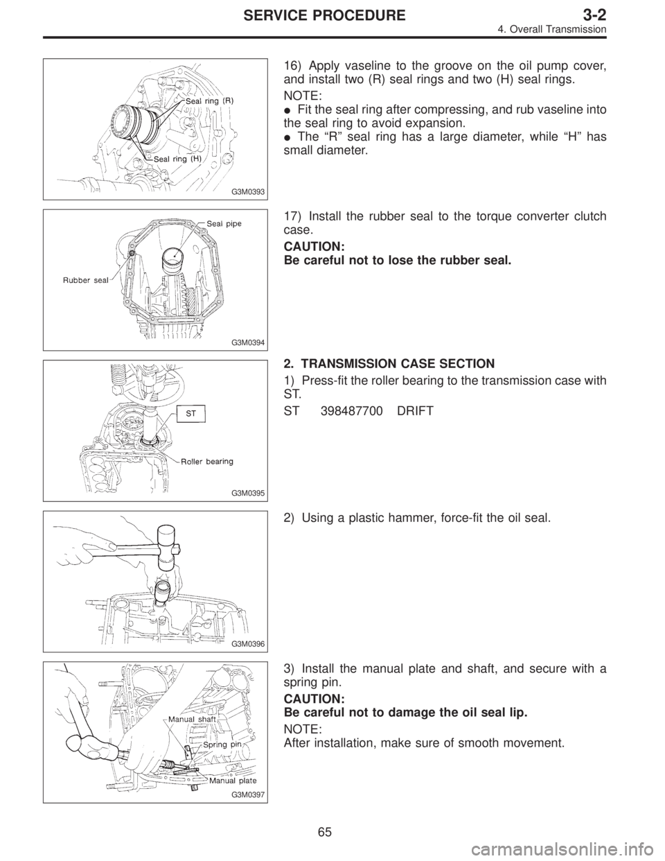
G3M0393
16) Apply vaseline to the groove on the oil pump cover,
and install two (R) seal rings and two (H) seal rings.
NOTE:
�Fit the seal ring after compressing, and rub vaseline into
the seal ring to avoid expansion.
�The“R”seal ring has a large diameter, while“H”has
small diameter.
G3M0394
17) Install the rubber seal to the torque converter clutch
case.
CAUTION:
Be careful not to lose the rubber seal.
G3M0395
2. TRANSMISSION CASE SECTION
1) Press-fit the roller bearing to the transmission case with
ST.
ST 398487700 DRIFT
G3M0396
2) Using a plastic hammer, force-fit the oil seal.
G3M0397
3) Install the manual plate and shaft, and secure with a
spring pin.
CAUTION:
Be careful not to damage the oil seal lip.
NOTE:
After installation, make sure of smooth movement.
65
3-2SERVICE PROCEDURE
4. Overall Transmission
Page 972 of 3342
 Assemble the manual lever and parking rod to the
inside shaft, and secure with a nut.
Tightening torque:
47±2 N⋅m (4.8±0.2 kg-m, 34.7±1.4 ft-lb)
G3M0364
5) Install the detention spring")
G3M0398
4) Assemble the manual lever and parking rod to the
inside shaft, and secure with a nut.
Tightening torque:
47±2 N⋅m (4.8±0.2 kg-m, 34.7±1.4 ft-lb)
G3M0364
5) Install the detention spring.
NOTE:
Position the spring so that its center is aligned with the
center of the manual plate.
Tightening torque:
6±1 N⋅m (0.6±0.1 kg-m, 4.3±0.7 ft-lb)
G3M0399
6) Install the lathe cut seal rings to the I.D./O.D. of the low
and reverse piston. Then install the piston into the case
with a press, ST1 and ST2.
ST1 398673600 COMPRESSOR
ST2 498627000 SEAT
CAUTION:
�Be careful not to tilt the piston when installing.
�Be careful not to damage the lip seal.
G3M0400
7) Install the one-way clutch inner race.
(1) Using a press and ST1, install the needle bearing
to the inner race.
ST1 398497701 INSTALLER
NOTE:
Use the following ST when removing.
ST 398527700 PULLER ASSY
B3M0403A
(2) Install four seal rings and thrust washer.
NOTE:
Apply vaseline to the groove of the inner race and to the
seal ring after installation, so that the seal ring will not
expand.
66
3-2SERVICE PROCEDURE
4. Overall Transmission
Page 973 of 3342
 Place the spring retainer on the inner race. Install
the spring to the recessed portion of the piston. Then
tighten eight socket head bolts from the rear side of the
transmission case.
Tig")
G3M0402
(3) Place the spring retainer on the inner race. Install
the spring to the recessed portion of the piston. Then
tighten eight socket head bolts from the rear side of the
transmission case.
Tightening torque:
25±2 N⋅m (2.5±0.2 kg-m, 18.1±1.4 ft-lb)
CAUTION:
Be sure to tighten evenly.
G3M0403
8) Install the band servo sub assembly.
9) Press the O.D. servo retainer into position with ST1 and
ST2, and secure with a snap ring.
ST1 498677010 COMPRESSOR
ST2 399703600 PULLER ASSY
CAUTION:
Perform the following operations with the transmis-
sion case set vertically on wooden blocks.
B3H0013A
10) Installation of the low & reverse brake:
(1) Install dish plate, driven plates, drive plates, and a
retaining plate, and secure with a snap ring.
NOTE:
�Pay attention to the orientation of the dish plate.
�Driven plate : 6
Drive plate : 6
�Dish plate : 1
�
1Snap ring
�
2Retaining plate
�
3Transmission case
�
4Lathe cut seal ring
�
5Dish plate
�
6Piston
�
7Bolt
�
8Lathe cut seal ring
�
9Clutch spring retainer
�
10Forward clutch drum
�
11Drive plate
�
12Driven plate
67
3-2SERVICE PROCEDURE
4. Overall Transmission
Page 980 of 3342
 Secure the housing with two nuts.
Tightening torque:
41±3 N⋅m (4.2±0.3 kg-m, 30.4±2.2 ft-lb)
G3M0394
3. TORQUE CONVERTER CLUTCH CASE AND
TRANSMISSION CASE
1) Apply proper amount of li")
G3M0424
(4) Secure the housing with two nuts.
Tightening torque:
41±3 N⋅m (4.2±0.3 kg-m, 30.4±2.2 ft-lb)
G3M0394
3. TORQUE CONVERTER CLUTCH CASE AND
TRANSMISSION CASE
1) Apply proper amount of liquid gasket (THREE BOND
Part No. 1215) to the entire torque converter clutch case
mating surface.
NOTE:
Make sure that the rubber seal and seal pipe are fitted in
position.
G3M0335
2) Install the torque converter clutch case assembly to the
transmission case assembly, and secure with six bolts and
four nuts.
Tightening torque:
41±3 N⋅m (4.2±0.3 kg-m, 30.4±2.2 ft-lb)
CAUTION:
When installing, be careful not to damage the torque
converter clutch case bushing and oil seal.
G3M0425
4. CONTROL VALVE AND OIL PAN
1) Install four accumulators with oil pans facing upward.
CAUTION:
Be careful not to confuse the springs and installation
positions.
�Spring specification
Unit: mm (in)
Accumulator spring Outer diameter Free length
1—2 28.5 (1.122) 44.5 (1.752)
2—3 20.5 (0.807) 31.0 (1.220)
3—4 17.3 (0.681) 43.7 (1.720)
N—D 17.8 (0.701) 36.5 (1.437)
74
3-2SERVICE PROCEDURE
4. Overall Transmission
Page 981 of 3342
G3M0367
2) Install and route the transmission harness.
CAUTION:
Be careful not to damage the harness.
B3M0418A
3) Install the control valve assembly.
(1) Set the select lever in range“2”.
(2) Install the two brackets, ATF temperature sensor
and the control valve by engaging the manual valve and
manual lever, then tighten the 17 bolts.
Tightening torque:
8±1 N⋅m (0.8±0.1 kg-m, 5.8±0.7 ft-lb)
CAUTION:
�Be careful not to pinch the harness roll the gasket.
�Tighten the control valve mounting bolts evenly.
B3M0419A
4) Install the oil strainer to the control valve. Be careful not
to cut or break the O-ring. Then tighten four bolts.
Tightening torque:
8±1 N⋅m (0.8±0.1 kg-m, 5.8±0.7 ft-lb)
B3M0420A
5) Secure four connectors.
75
3-2SERVICE PROCEDURE
4. Overall Transmission
Page 982 of 3342
 Install the oil cooler outlet pipe, and secure with two
bolts.
Tightening torque:
8±1 N⋅m (0.8±0.1 kg-m, 5.8±0.7 ft-lb)
CAUTION:
Fit the pipe into position. Be careful to avoid twistin")
G3M0345
6) Install the oil cooler outlet pipe, and secure with two
bolts.
Tightening torque:
8±1 N⋅m (0.8±0.1 kg-m, 5.8±0.7 ft-lb)
CAUTION:
Fit the pipe into position. Be careful to avoid twisting.
G3M0427
7) Install the oil pan.
(1) Attach the magnet at the specified position.
G3M0428
(2) With gasket inserted, secure the oil pan by tighten-
ing 20 bolts.
Tightening torque:
4.9±0.5 N⋅m (0.50±0.05 kg-m, 3.6±0.4 ft-lb)
NOTE:
Tighten the bolts evenly.
G3M0867
5. EXTENSION SECTION
NOTE:
When installing new oil seal into extension case, press it
with ST.
ST 498057300 INSTALLER
1) Install the filter in the extension case.
NOTE:
Pay attention to the orientation of the filter.
2) Install the transfer clutch valve assembly, transfer pipe,
and the stay then secure with five bolts.
Tightening torque:
8±1 N⋅m (0.8±0.1 kg-m, 5.8±0.7 ft-lb)
CAUTION:
�Be sure to tighten the going lead with one of these
bolts.
�Be sure to use a new gasket.
76
3-2SERVICE PROCEDURE
4. Overall Transmission
Page 983 of 3342
 Install the transfer clutch assembly to the case.
CAUTION:
Be careful not to damage the seal rings.
NOTE:
Insert the clutch assembly fully into position until the bear-
ing shoulder bottoms")
G3M0894
3) Install the transfer clutch assembly to the case.
CAUTION:
Be careful not to damage the seal rings.
NOTE:
Insert the clutch assembly fully into position until the bear-
ing shoulder bottoms.
G3M0429
6. CONNECTION OF EACH SECTION
1) Install vehicle speed sensor 1 on transmission case.
[FWD only]
Tightening torque:
7±1 N⋅m (0.7±0.1 kg-m, 5.1±0.7 ft-lb)
2) Install oil pipe.
G3M0339
3) Install the reduction driven gear.
4) Install the parking pawl and shaft, set the select lever in
the“P”range and tighten the drive pinion lock nut.
Tightening torque:
98±5 N⋅m (10.0±0.5 kg-m, 72.3±3.6 ft-lb)
NOTE:
After tightening, stake the lock nut securely.
G3M0895
5) Install the reduction drive gear assembly.
CAUTION:
Align mark on reduction drive gear with mark on driven
gear during installation.
NOTE:
Insert it fully into position until the bearing shoulder bot-
toms.
G3M0430
6) Measurement and adjustment of extension end play
(1) Measure distance L from end of extension case and
rear drive shaft with ST. (On FWD models, measure
distance from end of case to point at bearing location.)
ST 398643600 GAUGE
Unit: mm
L = Measured value�15
77
3-2SERVICE PROCEDURE
4. Overall Transmission
Page 985 of 3342
 Installation of extension case (AWD), transmission
cover (FWD) and transmission case.
�AWD model:
(1) Attach the selected thrust needle bearing to the end
surface of reduction drive gear wi")
G3M0896
7) Installation of extension case (AWD), transmission
cover (FWD) and transmission case.
�AWD model:
(1) Attach the selected thrust needle bearing to the end
surface of reduction drive gear with vaseline.
(2) Set the parking return spring.
(3) Remove the transfer clutch from the extension
case.
Set the needle bearing on the reduction drive shaft and
then install transfer clutch to the transfer clutch hub.
NOTE:
Be sure to engage the spline teeth correctly.
(4) With gasket inserted between them, install the
extension case to the transmission case.
CAUTION:
�Be sure to use a new gasket.
�After inserting the extension case halfway, connect
the connector for duty solenoid C. Be careful not to
jam the cord in the case.
�Be careful not to damage the rear drive shaft seal
ring.
(5) Tighten bolts to secure the case.
Tightening torque:
25±2 N⋅m (2.5±0.2 kg-m, 18.1±1.4 ft-lb)
�FWD model:
(1) Attach selected shim to transmission cover using
vaseline.
(2) Set the parking return spring.
(3) After positioning gasket, assemble transmission
cover and transmission case.
NOTE:
While aligning bearings, parking shaft, reduction driven
gear, etc. assemble the two cases.
(4) Tighten bolts.
Tightening torque:
25±2 N⋅m (2.5±0.2 kg-m, 18.1±1.4 ft-lb)
G3M0336
7. EXTERNAL PARTS
1) Install the vehicle speed sensor 1. (AWD only)
Tightening torque:
7±1 N⋅m (0.7±0.1 kg-m, 5.1±0.7 ft-lb)
79
3-2SERVICE PROCEDURE
4. Overall Transmission
 Install and route the transmission harness.
CAUTION:
Be careful not to damage the harness.
B3M0418A
3) Install the control valve assembly.
(1) Set the select lever in range“2”.
(2) Inst")