Page 1001 of 3342
 Measure dimension“A”of the drive pinion shaft.
G3M0462
2) Using a press, force-fit the roller bearing in position.
CAUTION:
Do not change the relative positions of the outer")
G3M0461
C: ASSEMBLY
1) Measure dimension“A”of the drive pinion shaft.
G3M0462
2) Using a press, force-fit the roller bearing in position.
CAUTION:
Do not change the relative positions of the outer race
and bearing cone.
3) After fitting the O-ring to the shaft, attach the drive pin-
ion collar to the shaft.
CAUTION:
Be careful not to damage the O-ring.
G3M0908
4) Tighten the lock washer and lock nut with ST1.
ST1 498937100 HOLDER
Actual tightening torque:
113±5 N⋅m (11.5±0.5 kg-m, 83.2±3.6 ft-lb)
NOTE:
�Pay attention to the orientation of lock washer.
�Tightening torque using torque wrench is determined by
the following equation:
T
1=72.2L + 72.2xT
T: Actual tightening torque
�Install ST2 to torque wrench as straight as possible.
ST2 499787100 WRENCH
G3M0464
5) Measure the starting torque of the bearing.
Make sure the starting torque is within the specified range.
If out of the allowable range, replace the roller bearing.
Starting torque:
0.3—2.0 N⋅m(3—20 kg-cm, 2.6—17.4 ft-lb)
94
3-2SERVICE PROCEDURE
8. Drive Pinion Shaft
Page 1017 of 3342
G3M0489
2) Install the washer and differential bevel gear to the dif-
ferential case (LH). Then put the case over the differential
case (RH), and connect both cases.
3) Install the crown gear and secure by tightening the bolt.
Standard tightening torque:
62±5 N⋅m (6.3±0.5 kg-m, 45.6±3.6 ft-lb)
G3M0491
4) Measurement of backlash (Selection of washer)
Measure the gear backlash with ST1 and ST2, and insert
ST2 through the access window of the case.
ST1 498247001 MAGNET BASE
ST2 498247100 DIAL GAUGE
Standard value:
0.13—0.18 mm (0.0051—0.0071 in)
NOTE:
Measure the backlash by applying a pinion tooth between
two bevel gear teeth.
G3M0492
5) Install the speedometer drive gear. Then force-fit the
taper roller bearing with a press and ST.
ST 398487700 DRIFT
CAUTION:
Be sure to position correctly the locking end of the
speedometer drive gear.
108
3-2SERVICE PROCEDURE
14. Differential Case Assembly
Page 1024 of 3342
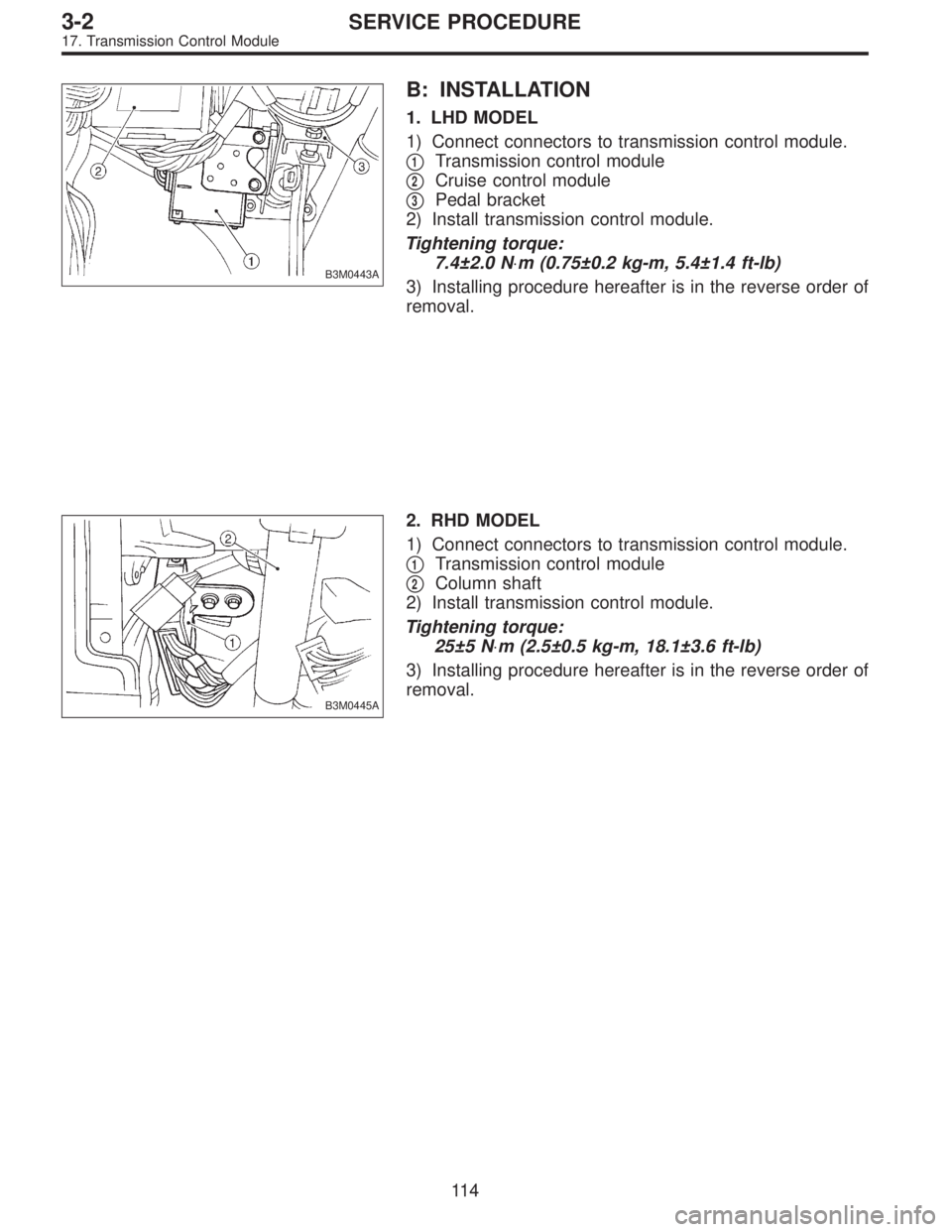
B3M0443A
B: INSTALLATION
1. LHD MODEL
1) Connect connectors to transmission control module.
�
1Transmission control module
�
2Cruise control module
�
3Pedal bracket
2) Install transmission control module.
Tightening torque:
7.4±2.0 N⋅m (0.75±0.2 kg-m, 5.4±1.4 ft-lb)
3) Installing procedure hereafter is in the reverse order of
removal.
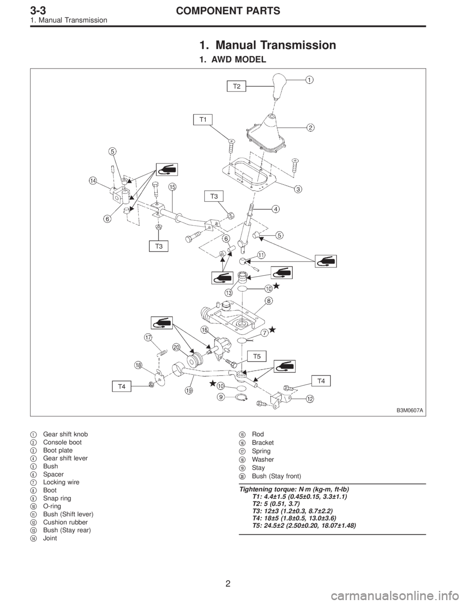
B3M0445A
2. RHD MODEL
1) Connect connectors to transmission control module.
�
1Transmission control module
�
2Column shaft
2) Install transmission control module.
Tightening torque:
25±5 N⋅m (2.5±0.5 kg-m, 18.1±3.6 ft-lb)
3) Installing procedure hereafter is in the reverse order of
removal.
11 4
3-2SERVICE PROCEDURE
17. Transmission Control Module
Page 1025 of 3342
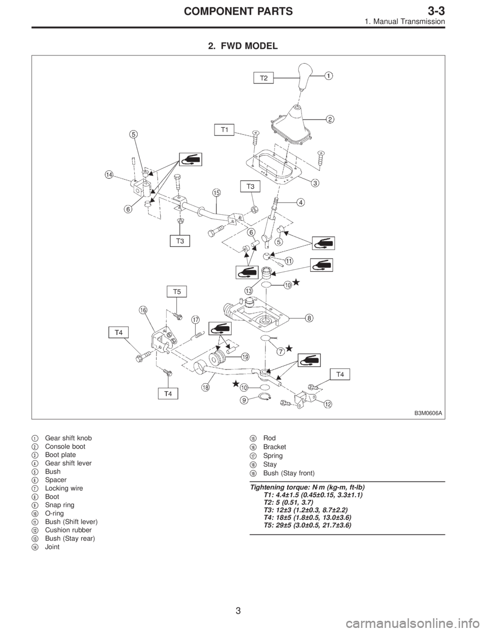
1. Manual Transmission
1. AWD MODEL
B3M0607A
�1Gear shift knob
�
2Console boot
�
3Boot plate
�
4Gear shift lever
�
5Bush
�
6Spacer
�
7Locking wire
�
8Boot
�
9Snap ring
�
10O-ring
�
11Bush (Shift lever)
�
12Cushion rubber
�
13Bush (Stay rear)
�
14Joint�
15Rod
�
16Bracket
�
17Spring
�
18Washer
�
19Stay
�
20Bush (Stay front)
Tightening torque: N⋅m (kg-m, ft-lb)
T1: 4.4±1.5 (0.45±0.15, 3.3±1.1)
T2: 5 (0.51, 3.7)
T3: 12±3 (1.2±0.3, 8.7±2.2)
T4: 18±5 (1.8±0.5, 13.0±3.6)
T5: 24.5±2 (2.50±0.20, 18.07±1.48)
2
3-3COMPONENT PARTS
1. Manual Transmission
Page 1026 of 3342
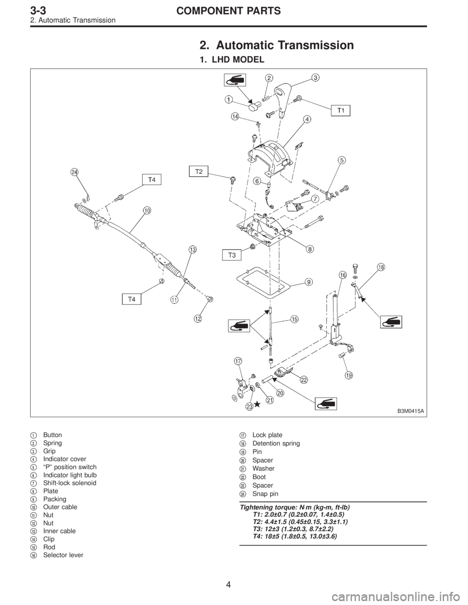
2. FWD MODEL
B3M0606A
�1Gear shift knob
�
2Console boot
�
3Boot plate
�
4Gear shift lever
�
5Bush
�
6Spacer
�
7Locking wire
�
8Boot
�
9Snap ring
�
10O-ring
�
11Bush (Shift lever)
�
12Cushion rubber
�
13Bush (Stay rear)
�
14Joint�
15Rod
�
16Bracket
�
17Spring
�
18Stay
�
19Bush (Stay front)
Tightening torque: N⋅m (kg-m, ft-lb)
T1: 4.4±1.5 (0.45±0.15, 3.3±1.1)
T2: 5 (0.51, 3.7)
T3: 12±3 (1.2±0.3, 8.7±2.2)
T4: 18±5 (1.8±0.5, 13.0±3.6)
T5: 29±5 (3.0±0.5, 21.7±3.6)
3
3-3COMPONENT PARTS
1. Manual Transmission
Page 1027 of 3342
2. Automatic Transmission
1. LHD MODEL
B3M0415A
�1Button
�
2Spring
�
3Grip
�
4Indicator cover
�
5“P” position switch
�
6Indicator light bulb
�
7Shift-lock solenoid
�
8Plate
�
9Packing
�
10Outer cable
�
11Nut
�
12Nut
�
13Inner cable
�
14Clip
�
15Rod
�
16Selector lever�
17Lock plate
�
18Detention spring
�
19Pin
�
20Spacer
�
21Washer
�
22Boot
�
23Spacer
�
24Snap pin
Tightening torque: N⋅m (kg-m, ft-lb)
T1: 2.0±0.7 (0.2±0.07, 1.4±0.5)
T2: 4.4±1.5 (0.45±0.15, 3.3±1.1)
T3: 12±3 (1.2±0.3, 8.7±2.2)
T4: 18±5 (1.8±0.5, 13.0±3.6)
4
3-3COMPONENT PARTS
2. Automatic Transmission
Page 1028 of 3342
2. RHD MODEL
B3M0385A
�1Grip
�
2Spring
�
3Button
�
4Indicator cover
�
5“P”position switch
�
6Indicator light bulb
�
7Shift-lock solenoid
�
8Plate
�
9Packing
�
10Outer cable
�
11Nut
�
12Nut
�
13Inner cable
�
14Clip
�
15Rod�
16Selector lever
�
17Lock plate
�
18Detention spring
�
19Pin
�
20Spacer
�
21Washer
�
22Boot
�
23Spacer
�
24Snap pin
Tightening torque: N⋅m (kg-m, ft-lb)
T1: 4.4±1.5 (0.45±0.15, 3.3±1.1)
T2: 12±3 (1.2±0.3, 8.7±2.2)
T3: 18±5 (1.8±0.5, 13.0±3.6)
5
3-3COMPONENT PARTS
2. Automatic Transmission
Page 1032 of 3342
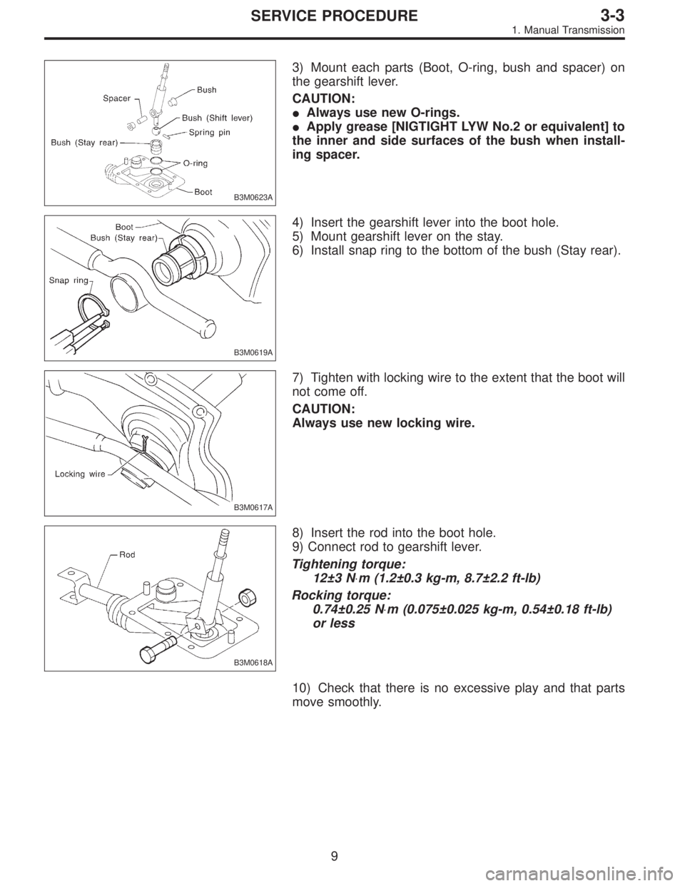
B3M0623A
3) Mount each parts (Boot, O-ring, bush and spacer) on
the gearshift lever.
CAUTION:
�Always use new O-rings.
�Apply grease [NIGTIGHT LYW No.2 or equivalent] to
the inner and side surfaces of the bush when install-
ing spacer.
B3M0619A
4) Insert the gearshift lever into the boot hole.
5) Mount gearshift lever on the stay.
6) Install snap ring to the bottom of the bush (Stay rear).
B3M0617A
7) Tighten with locking wire to the extent that the boot will
not come off.
CAUTION:
Always use new locking wire.
B3M0618A
8) Insert the rod into the boot hole.
9) Connect rod to gearshift lever.
Tightening torque:
12±3 N⋅m (1.2±0.3 kg-m, 8.7±2.2 ft-lb)
Rocking torque:
0.74±0.25 N⋅m (0.075±0.025 kg-m, 0.54±0.18 ft-lb)
or less
10) Check that there is no excessive play and that parts
move smoothly.
9
3-3SERVICE PROCEDURE
1. Manual Transmission
 Install the washer and differential bevel gear to the dif-
ferential case (LH). Then put the case over the differential
case (RH), and connect both cases.
3) Install the crown gear and secu")