Page 47 of 3342
BRAKES
[ABS
5
.31
TYPE]
[T7A3]
4-4d
7
.
Diagnostics
Chart
for
ABS
Warning
Light
Circuit
and
Diagnosis
Circuit
Failure
B1
2345
678910
1112
1
13
1
14
1
15
1
16
1
17
1
18
1
19
.
)
D
V
-
B4M1273A
I7A1
ICHONECK
IF
OTHER
WARNING
LIGHTS
TURN
Turn
ignition
switch
to
ON
(engine
OFF)
.
CHECK
:
Do
other
warning
lights
turn
on?
,rES
:
Go
to
step
7A2
.
No
:
Repair
combination
meter
.
7A2
I
CHECK
ABS
WARNING
LIGHT
BULB
.
1)
Turn
ignition
switch
to
OFF
.
2)
Remove
combination
meter
.
3)
Remove
ABS
warning
light
bulb
from
combination
meter
.
CHECK
:
Is
ABS
warning
light
bulb
OK?
,mss
:
Go
to
step
7A3
.
No
:
Replace
ABS
warning
light
bulb
.
7A3
CHECK
BATTERY
NG
LIGHT
HARNESS
SHO
RT
OF
ABS
WARN-
1)
Disconnect
connector
(B100)
from
connector
(F2)
.
2)
Measure
voltage
between
connector
(B100)
and
chas-
sis
ground
.
Connector
&
terminal
(B100)
No
.
9
(+)
-
Chassis
ground
(
)
:
CHECK
:
Is
thevoltage
less
than
3
V?
vES
:
Go
to
step
7A4
.
No
:
Repair
warning
light
harness
.
19
Page 48 of 3342
4-4d
[r7aa1
BRAKES
[ABS
5
.31
TYPE]
7
.
DiagnosticsChart
for
ABS
Warning
Light
Circuit
and
Diagnosis
Circuit
Failure
2345
67890
B1~
1
11
1
12
1
13
1
14
1516
171819
1:
)
D
84M1273A
7A4
CHECK
BATTERY
NG
LIGHT
HARN
SSORT
OF
ABS
WARN-
1)
Turn
ignition
switch
to
ON
.
2)
Measure
voltage
between
connector
(B100)
and
chas-
sis
ground
.
Connector
&
terminal
(8100)
No
.
9
(+)
-
Chassis
ground
(
)
:
CHECK
:
is
voltage
less
than3
V?
YES
:
Go
to
step
7A5
.
No
:
Repair
warning
light
harness
.
7A5
CHECK
WIRING
HARNESS
.
1)
Turn
ignition
switch
to
OFF
.
2)
Install
ABS
warning
light
bulb
from
combination
meter
.
3)
Install
combination
meter
.
4)
Turn
ignition
switch
to
ON
.
5)
Measure
voltage
between
connector
(B100)
and
chas-
sis
ground
.
Connector
&
terminal
(B100)
No
.
9
(+)
-
Chassis
ground
(-)
:
CHECK
:
Is
voltage
between
10
V
and
15
V?
,rES
:
Go
to
step
7A6
.
No
:
Repair
wiring
harness
.
20
Page 438 of 3342
 O")
1. Engine Lubrication System
Before troubleshooting, make sure that the engine oil level
is correct and no oil leakage exists.
Trouble Possible cause Corrective action
1. Warning light remains
on.1) Oil pressure switch
failureCracked diaphragm or oil leakage within switch Replace.
Broken spring or seized contacts Replace.
2) Low oil pressureClogged oil filter Replace.
Malfunction of oil by-pass valve of oil filter Clean or replace.
Malfunction of oil relief valve of oil pump Clean or replace.
Clogged oil passage Clean.
Excessive tip clearance and side clearance of oil
pump rotor and gearReplace.
Clogged oil strainer or broken pipe Clean or replace.
3) No oil pressureInsufficient engine oil Replenish.
Broken pipe of oil strainer Replace.
Stuck oil pump rotor Replace.
2. Warning light does not
go on.1) Burn-out bulb Replace.
2) Poor contact of switch contact points Replace.
3) Disconnection of wiring Repair.
3. Warning light flickers
momentarily.1) Poor contact at terminals Repair.
2) Defective wiring harness Repair.
3) Low oil pressureCheck for the same pos-
sible causes as listed in
1.—2)
17
2-4DIAGNOSTICS
1. Engine Lubrication System
Page 1027 of 3342
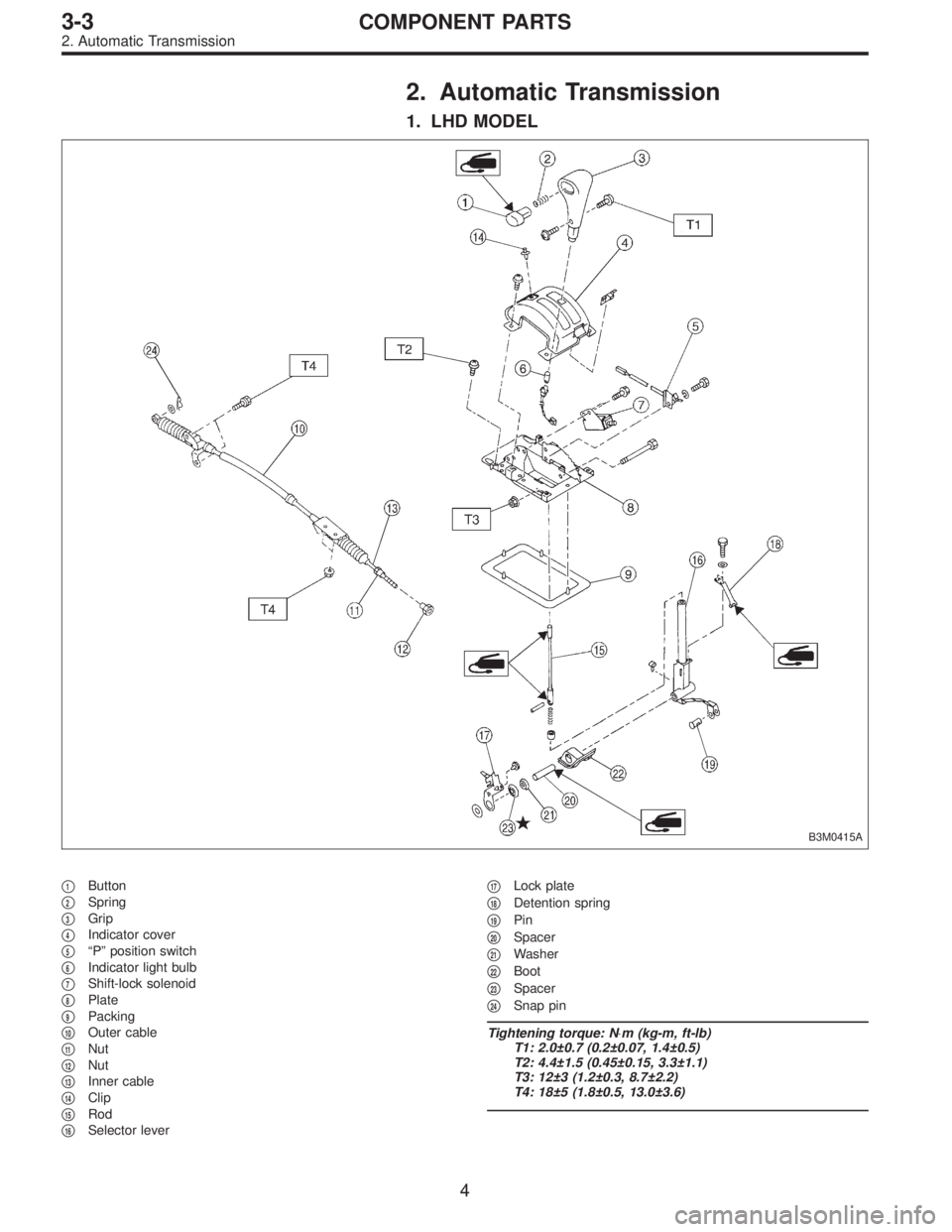
2. Automatic Transmission
1. LHD MODEL
B3M0415A
�1Button
�
2Spring
�
3Grip
�
4Indicator cover
�
5“P” position switch
�
6Indicator light bulb
�
7Shift-lock solenoid
�
8Plate
�
9Packing
�
10Outer cable
�
11Nut
�
12Nut
�
13Inner cable
�
14Clip
�
15Rod
�
16Selector lever�
17Lock plate
�
18Detention spring
�
19Pin
�
20Spacer
�
21Washer
�
22Boot
�
23Spacer
�
24Snap pin
Tightening torque: N⋅m (kg-m, ft-lb)
T1: 2.0±0.7 (0.2±0.07, 1.4±0.5)
T2: 4.4±1.5 (0.45±0.15, 3.3±1.1)
T3: 12±3 (1.2±0.3, 8.7±2.2)
T4: 18±5 (1.8±0.5, 13.0±3.6)
4
3-3COMPONENT PARTS
2. Automatic Transmission
Page 1028 of 3342
2. RHD MODEL
B3M0385A
�1Grip
�
2Spring
�
3Button
�
4Indicator cover
�
5“P”position switch
�
6Indicator light bulb
�
7Shift-lock solenoid
�
8Plate
�
9Packing
�
10Outer cable
�
11Nut
�
12Nut
�
13Inner cable
�
14Clip
�
15Rod�
16Selector lever
�
17Lock plate
�
18Detention spring
�
19Pin
�
20Spacer
�
21Washer
�
22Boot
�
23Spacer
�
24Snap pin
Tightening torque: N⋅m (kg-m, ft-lb)
T1: 4.4±1.5 (0.45±0.15, 3.3±1.1)
T2: 12±3 (1.2±0.3, 8.7±2.2)
T3: 18±5 (1.8±0.5, 13.0±3.6)
5
3-3COMPONENT PARTS
2. Automatic Transmission
Page 1445 of 3342
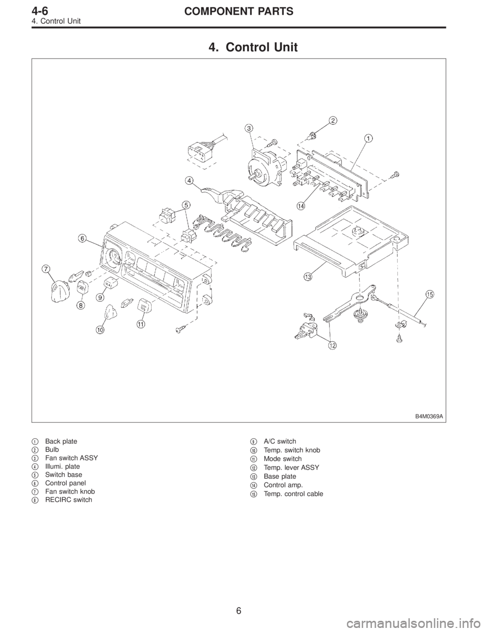
4. Control Unit
B4M0369A
�1Back plate
�
2Bulb
�
3Fan switch ASSY
�
4Illumi. plate
�
5Switch base
�
6Control panel
�
7Fan switch knob
�
8RECIRC switch�
9A/C switch
�
10Temp. switch knob
�
11Mode switch
�
12Temp. lever ASSY
�
13Base plate
�
14Control amp.
�
15Temp. control cable
6
4-6COMPONENT PARTS
4. Control Unit
Page 1499 of 3342

2. Performance Test Diagnosis
If various conditions caused to other air conditioning
system, the characteristics revealed on manifold gauge
reading are shown in the following:
As to the method of a performance test, refer to the item
of“Performance Test”.
Each shaded area on the following tables indicates a read-
ing of the normal system when the temperature of outside
air is 32.5°C (91°F).
Condition Probable cause Corrective action
INSUFFICIENT REFRIGERANT CHARGE
G4M0673
Insufficient cooling Refrigerant is small, or
leaking a little.1. Perform leak test.
2. Repair leak.
3. Charge system.
Evacuate, as
necessary, and
recharge system.
ALMOST NO REFRIGERANT
G4M0674
No cooling action Serious refrigerant leak.Stop compressor
immediately.
1. Perform leak test.
2. Discharge system.
3. Repair leak(s).
4. Replace receiver
drier if necessary.
5. Check oil level.
6. Evacuate and
recharge system.
FAULTY EXPANSION VALVE
G4M0675
Slight cooling;
Sweating or frosted
expansion valve inlet.Expansion valve
restricts refrigerant flow.
�Expansion valve is
clogged.
�Expansion valve is
inoperative.
Valve stuck closed.
Thermal bulb has lost
charge.If valve inlet reveals
sweat or frost:
1. Discharge system.
2. Remove valve and
clean it. Replace it if
necessary.
3. Evacuate system.
4. Charge system.
If valve does not oper-
ate:
1. Discharge system.
2. Replace valve.
3. Evacuate and charge
system.
42
4-7DIAGNOSTICS
2. Performance Test Diagnosis
Page 1736 of 3342
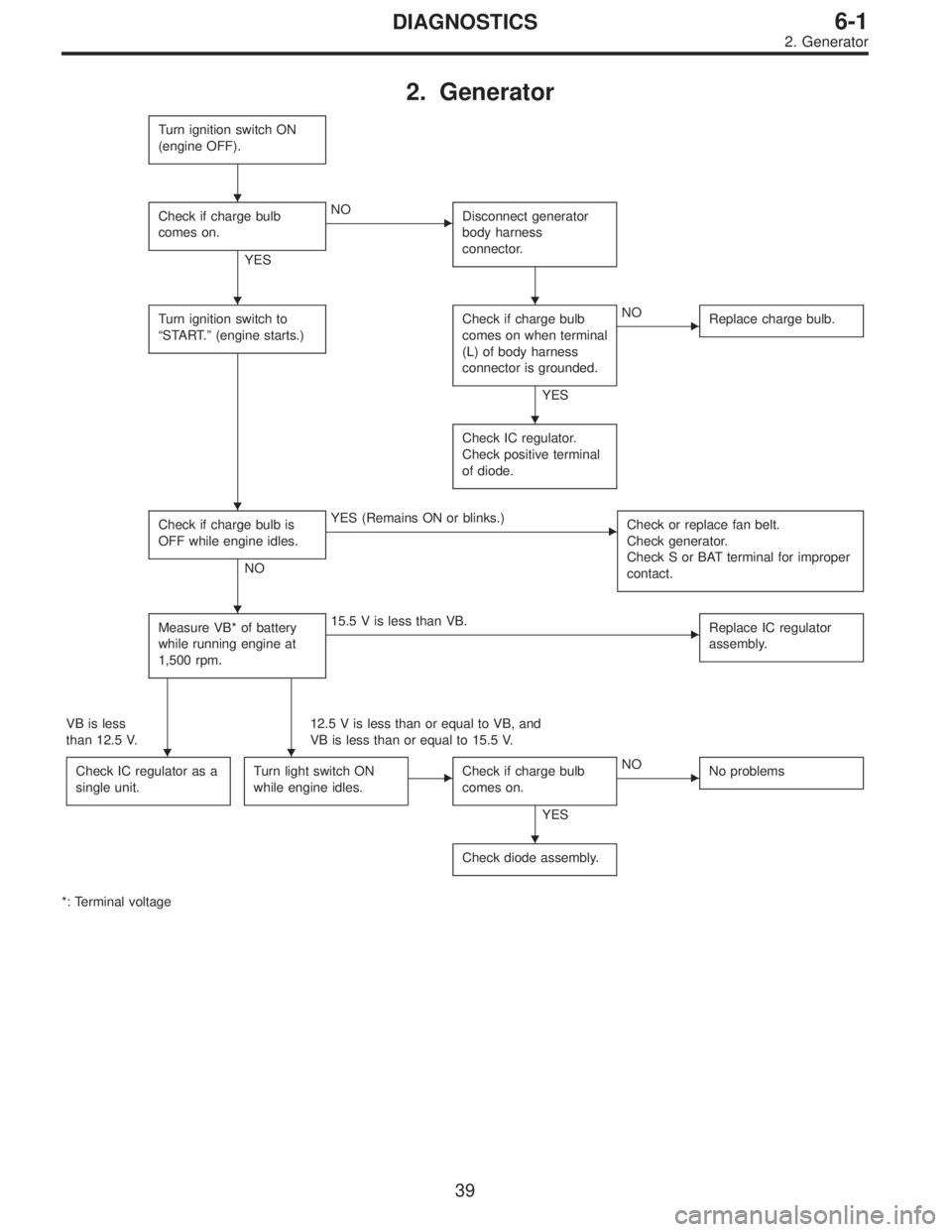
2. Generator
Turn ignition switch ON
(engine OFF).
Check if charge bulb
comes on.
YES
�NO
Disconnect generator
body harness
connector.
Turn ignition switch to
“START.”(engine starts.)Check if charge bulb
comes on when terminal
(L) of body harness
connector is grounded.
YES
�NO
Replace charge bulb.
Check IC regulator.
Check positive terminal
of diode.
Check if charge bulb is
OFF while engine idles.
NO
�YES (Remains ON or blinks.)
Check or replace fan belt.
Check generator.
Check S or BAT terminal for improper
contact.
Measure VB* of battery
while running engine at
1,500 rpm.�15.5 V is less than VB.
Replace IC regulator
assembly.
VB is less
than 12.5 V.12.5 V is less than or equal to VB, and
VB is less than or equal to 15.5 V.
Check IC regulator as a
single unit.
Turn light switch ON
while engine idles.�Check if charge bulb
comes on.
YES
�NO
No problems
Check diode assembly.
*: Terminal voltage
�
��
�
�
�
��
�
39
6-1DIAGNOSTICS
2. Generator
![SUBARU LEGACY 1997 Service Repair Manual
BRAKES
[ABS
5
.31
TYPE]
[T7A3]
4-4d
7
.
Diagnostics
Chart
for
ABS
Warning
Light
Circuit
and
Diagnosis
Circuit
Failure
B1
2345
678910
1112
1
13
1
14
1
15
1
16
1
17
1
18
1
19
.
)
D
V
-
B4M1273A
I](/manual-img/17/57434/w960_57434-46.png "SUBARU LEGACY 1997 Service Repair Manual
BRAKES
[ABS
5
.31
TYPE]
[T7A3]
4-4d
7
.
Diagnostics
Chart
for
ABS
Warning
Light
Circuit
and
Diagnosis
Circuit
Failure
B1
2345
678910
1112
1
13
1
14
1
15
1
16
1
17
1
18
1
19
.
)
D
V
-
B4M1273A
I")
![SUBARU LEGACY 1997 Service Repair Manual
4-4d
[r7aa1
BRAKES
[ABS
5
.31
TYPE]
7
.
DiagnosticsChart
for
ABS
Warning
Light
Circuit
and
Diagnosis
Circuit
Failure
2345
67890
B1~
1
11
1
12
1
13
1
14
1516
171819
1:
)
D
84M1273A
7A4
CHECK
BATT](/manual-img/17/57434/w960_57434-47.png "SUBARU LEGACY 1997 Service Repair Manual
4-4d
[r7aa1
BRAKES
[ABS
5
.31
TYPE]
7
.
DiagnosticsChart
for
ABS
Warning
Light
Circuit
and
Diagnosis
Circuit
Failure
2345
67890
B1~
1
11
1
12
1
13
1
14
1516
171819
1:
)
D
84M1273A
7A4
CHECK
BATT")