Page 2619 of 3342
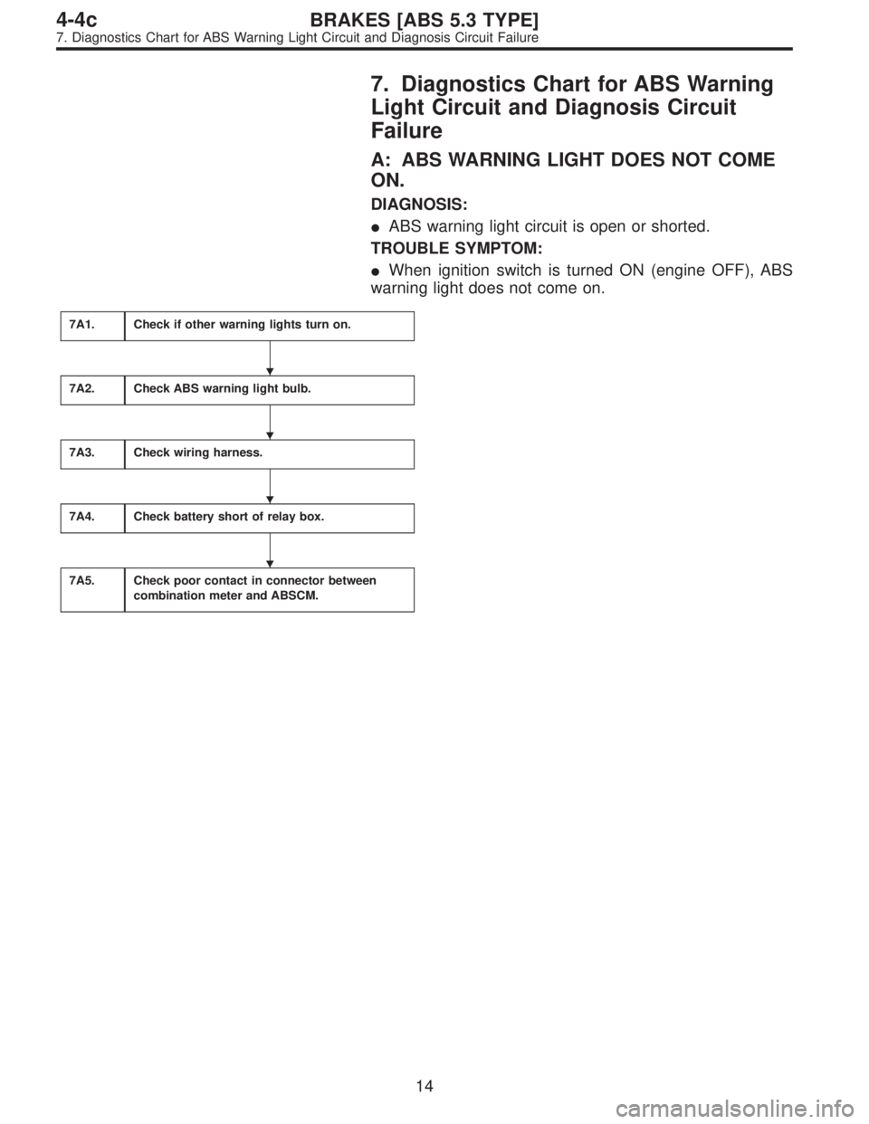
7. Diagnostics Chart for ABS Warning
Light Circuit and Diagnosis Circuit
Failure
A: ABS WARNING LIGHT DOES NOT COME
ON.
DIAGNOSIS:
�ABS warning light circuit is open or shorted.
TROUBLE SYMPTOM:
�When ignition switch is turned ON (engine OFF), ABS
warning light does not come on.
7A1.Check if other warning lights turn on.
7A2.Check ABS warning light bulb.
7A3.Check wiring harness.
7A4.Check battery short of relay box.
7A5.Check poor contact in connector between
combination meter and ABSCM.
�
�
�
�
14
4-4cBRAKES [ABS 5.3 TYPE]
7. Diagnostics Chart for ABS Warning Light Circuit and Diagnosis Circuit Failure
Page 2621 of 3342
7A2
CHECK ABS WARNING LIGHT BULB.
1) Turn ignition switch to OFF.
2) Remove combination meter.
3) Remove ABS warning light bulb from combination
meter.
: Is ABS warning light bulb OK?
: Go to step7A3.
: Replace ABS warning light bulb.
B4M0791A
7A3
CHECK WIRING HARNESS.
1) Disconnect connector from ABSCM.
2) Disconnect connector (F50) from relay box.
3) Turn ignition switch to ON.
4) Measure voltage between connector (F49) and chassis
ground.
: Connector & terminal
(F49) No. 54 (+) — Chassis ground (�):
Is voltage 12 V?
: Go to next step.
: Repair broken wire in harness or connector.
5) Turn ignition switch to OFF.
6) Measure voltage between ABSCM connector (F49) and
chassis ground.
: Connector & terminal
(F49) No. 54 (+) — Chassis ground (�):
Is voltage less than 3 V?
: Go to step7A4.
: Repair battery short of harness.
16
4-4cBRAKES [ABS 5.3 TYPE]
7. Diagnostics Chart for ABS Warning Light Circuit and Diagnosis Circuit Failure
Page 2893 of 3342
7A1CHECK IF OTHER WARNING LIGHTS
TURN ON.
Turn ignition switch to ON (engine OFF).
: Do other warning lights turn on?
: Go to step7A2.
: Repair combination meter.
7A2
CHECK ABS WARNING LIGHT BULB.
1) Turn ignition switch to OFF.
2) Remove combination meter.
3) Remove ABS warning light bulb from combination
meter.
: Is ABS warning light bulb OK?
: Go to step7A3.
: Replace ABS warning light bulb.
B4M1273A
7A3CHECK BATTERY SHORT OF ABS
WARNING LIGHT HARNESS.
1) Disconnect connector (B100) from connector (F2).
2) Measure voltage between connector (B100) and chas-
sis ground.
Connector & terminal
(B100) No. 9 (+) — Chassis ground (�):
: Is the voltage less than 3 V?
: Go to step7A4.
: Repair warning light harness.
17
4-4dBRAKES [ABS 5.3i TYPE]
7. Diagnostics Chart for ABS Warning Light Circuit and Diagnosis Circuit Failure
Page 2894 of 3342
B4M1273A
7A4CHECK BATTERY SHORT OF ABS
WARNING LIGHT HARNESS.
1) Turn ignition switch to ON.
2) Measure voltage between connector (B100) and chas-
sis ground.
Connector & terminal
(B100) No. 9 (+)—Chassis ground (�):
: Is voltage less than 3 V?
: Go to step7A5.
: Repair warning light harness.
B4M1273A
7A5
CHECK WIRING HARNESS.
1) Turn ignition switch to OFF.
2) Install ABS warning light bulb from combination meter.
3) Install combination meter.
4) Turn ignition switch to ON.
5) Measure voltage between connector (B100) and chas-
sis ground.
Connector & terminal
(B100) No. 9 (+)—Chassis ground (�):
: Is voltage between 10 V and 15 V?
: Go to step7A6.
: Repair wiring harness.
18
4-4dBRAKES [ABS 5.3i TYPE]
7. Diagnostics Chart for ABS Warning Light Circuit and Diagnosis Circuit Failure
Page 3158 of 3342
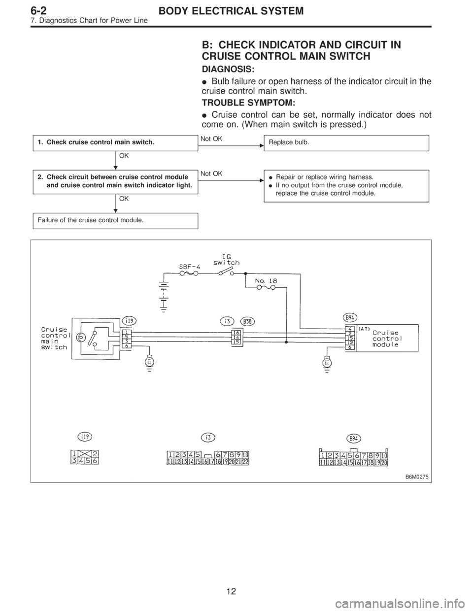
B: CHECK INDICATOR AND CIRCUIT IN
CRUISE CONTROL MAIN SWITCH
DIAGNOSIS:
�Bulb failure or open harness of the indicator circuit in the
cruise control main switch.
TROUBLE SYMPTOM:
�Cruise control can be set, normally indicator does not
come on. (When main switch is pressed.)
1. Check cruise control main switch.
OK
�Not OK
Replace bulb.
2. Check circuit between cruise control module
and cruise control main switch indicator light.
OK
�Not OK
�Repair or replace wiring harness.
�If no output from the cruise control module,
replace the cruise control module.
Failure of the cruise control module.
B6M0275
�
�
12
6-2BODY ELECTRICAL SYSTEM
7. Diagnostics Chart for Power Line
Page:
< prev 1-8 9-16 17-24
 Turn ignition switch to OFF.
2) Remove combination meter.
3) Remove ABS warning light bulb from combination
meter.
: Is ABS warning light bulb OK?
: Go to step7A3.")
.
: Do other warning lights turn on?
: Go to step7A2.
: Repair combination meter.
7A2
CHECK ABS WARNING LIGHT BULB.
1)")
 Turn ignition switch to ON.
2) Measure voltage between connector (B100) and chas-
sis ground.
Connector & terminal
(B100) No. 9 (+)—C")