Page 1747 of 3342
B6M0336A
2) Look at the beam angle gauge (vertical movement).
The bubble on the gauge should not deviate from the cen-
ter of the gauge.
B6M0825A
3) Look at the beam angle gauge (horizontal movement).
The indicator should not deviate from the center of the
gauge by more than two segments on either side of the
gauge.
B: REMOVAL AND INSTALLATION
1. HEADLIGHT BULB
1) Disconnect the connector from inside of the engine
compartment.
2) Remove rubber cap.
3) Remove the light bulb retaining spring to remove the
bulb.
4) Replace the bulb with a new one and hook the spring.
5) Attach the rubber cap and connect the connector.
M6A0139
CAUTION:
�Since the tungsten halogen bulb operates at high
temperature, dirt and oil on the bulb surface decreases
the bulb’s useful life. When replacing the bulb, hold the
flange portion and do not touch the glass portion.
9
6-2SERVICE PROCEDURE
4. Headlight
Page 1776 of 3342
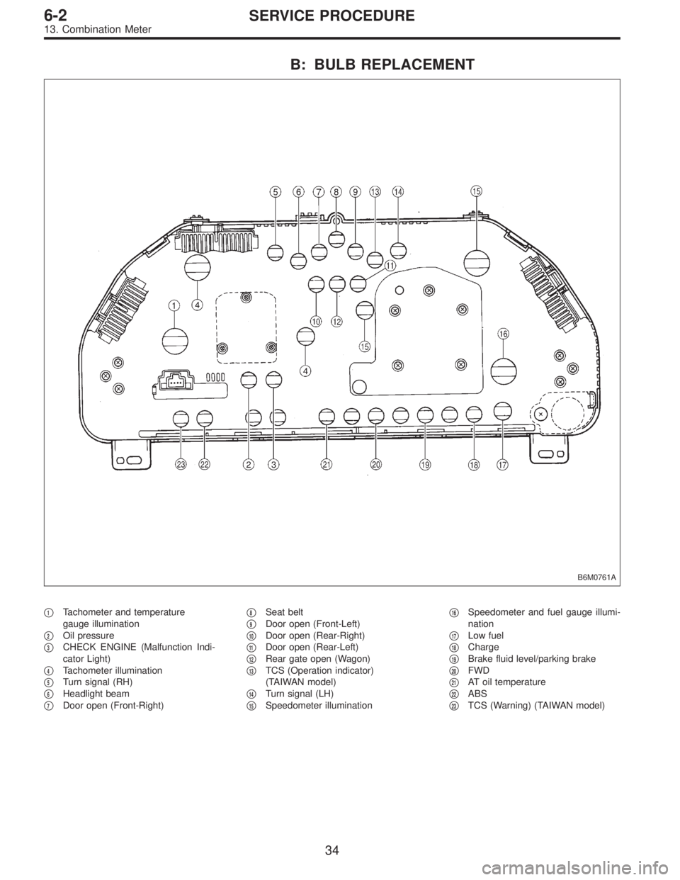
B: BULB REPLACEMENT
B6M0761A
�1Tachometer and temperature
gauge illumination
�
2Oil pressure
�
3CHECK ENGINE (Malfunction Indi-
cator Light)
�
4Tachometer illumination
�
5Turn signal (RH)
�
6Headlight beam
�
7Door open (Front-Right)�
8Seat belt
�
9Door open (Front-Left)
�
10Door open (Rear-Right)
�
11Door open (Rear-Left)
�
12Rear gate open (Wagon)
�
13TCS (Operation indicator)
(TAIWAN model)
�
14Turn signal (LH)
�
15Speedometer illumination�
16Speedometer and fuel gauge illumi-
nation
�
17Low fuel
�
18Charge
�
19Brake fluid level/parking brake
�
20FWD
�
21AT oil temperature
�
22ABS
�
23TCS (Warning) (TAIWAN model)
34
6-2SERVICE PROCEDURE
13. Combination Meter
Page 1835 of 3342

D: BASIC DIAGNOSTICS PROCEDURE
Start security system check.
Fully open all door windows and turn ignition switch OFF.
Take key out of ignition, exit vehicle and lock driver’s door.
Indicator light illuminates.
OK The light flashes.
� The light does not
illuminate.
Check indicator harness.
Check security indicator light.
Check driver’s door key cylinder lock/unlock switch.
Check security control module.
Check whether switch input signal remains UNLOCK.
Check wiring harness.
Check switch input signals.
(Harnesses and switches separately)
(Tamper, door, hood, trunk and rear gate
switch)Check security control module.
Wait for 30 seconds.
Indicator light flashes at long intervals (0.2 sec. ON and 2.4 sec.
OFF).
OK
� Not OK
Check security control module.
Unlock driver’s door using the inside lock knob and open door.
The horn sounds and headlights flash intermittently at 0.2 sec. ON
and 0.6 sec. OFF intervals.
The engine will not start even if the ignition switch is turned to
START. Indicator lamp goes out.
OK Starter motor runs.
� All are not OK.
Check driver’s door switch.
Check wiring harness.
Check security control module.
� Horn is not OK.
Check horn
operation by
pushing horn pad
on steering wheel.
OK
� Not OK
Check horn.
Check horn relay.
Check security control module.
Check harness between horn relay and security control module.
� Headlights are not
OK.
Check headlights
operation by
turning light switch
ON/OFF.
OK
� Not OK
Check headlight
bulbs.
Check combination
switch.
Check headlight
relay.
Check starter interrupt relay.
Check wiring harness.
Check security control module.Check headlight alarm relay.
Check security control module.
Check wiring harness.
The alarm system continues to operate for 150 seconds.
OK Not OK
The horn and
headlights turn off.
The starter motor
does not run.
OK
� Not OK
Check security
control module.
Unlock the driver’s door using ignition key.
Continues to next step.
�
�
�
�
�
�
�
�
�
��
�
��
�
�
90
6-2DIAGNOSTICS
6. Security System
Page 1941 of 3342
B2M0510A
7A3CHECK HARNESS BETWEEN COMBINA-
TION METER AND IGNITION SWITCH
CONNECTOR.
1) Turn ignition switch to ON.
2) Measure voltage between combination meter connector
and chassis ground.
: Connector & terminal
(i14) No. 11 (+)—Chassis ground (�):
Is voltage more than 10 V?
: Go to next.
: Check the following and repair if necessary.
�Blown out fuse (No. 15).
NOTE:
If replaced fuse (No. 15) blows easily, check the harness
for short circuit of harness between fuse (No. 15) and com-
bination meter connector.
�Open or short circuit in harness between fuse (No. 15)
and combination meter connector
�Open or short circuit in harness between fuse (No. 15)
and ignition switch connector
�Poor contact in ignition switch connector
: Is there poor contact in combination meter
connector?
: Repair poor contact in combination meter connec-
tor.
: Replace bulb or combination meter.
90
2-7ON-BOARD DIAGNOSTICS II SYSTEM
7. Diagnostics for CHECK ENGINE Malfunction Indicator Lamp (MIL)
Page 2479 of 3342
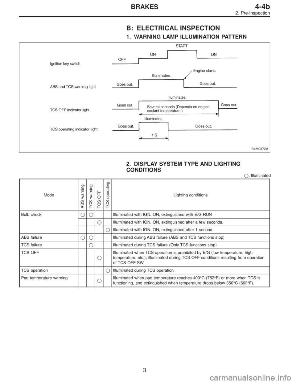
B: ELECTRICAL INSPECTION
1. WARNING LAMP ILLUMINATION PATTERN
B4M0372A
2. DISPLAY SYSTEM TYPE AND LIGHTING
CONDITIONS
�: Illuminated
Mode
ABS warning
TCS warning
TCS OFF
TCS operating
Lighting conditions
Bulb check��Illuminated with IGN. ON, extinguished with E/G RUN
�Illuminated with IGN. ON, extinguished after a few seconds.
�Illuminated with IGN. ON, extinguished after 1 second.
ABS failure��Illuminated during ABS failure (ABS and TCS functions stop)
TCS failure�Illuminated during TCS failure (Only TCS functions stop)
TCS OFF
�Illuminated when TCS operation is prohibited by E/G (low temperature, high
temperature, etc.); illuminated during TCS OFF conditions resulting from operation
of TCS OFF SW.
TCS operation�Illuminated during TCS operation
Pad temperature warning
�Illuminated when pad temperature reaches 400°C (752°F) or more when TCS is
functioning, and extinguished when temperature drops below 350°C (662°F).
3
4-4bBRAKES
2. Pre-inspection
Page 2508 of 3342
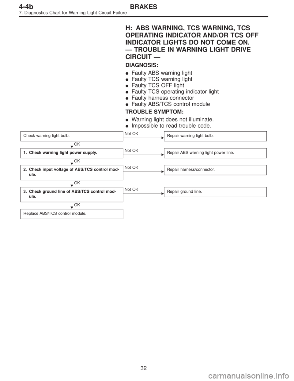
H: ABS WARNING, TCS WARNING, TCS
OPERATING INDICATOR AND/OR TCS OFF
INDICATOR LIGHTS DO NOT COME ON.
—TROUBLE IN WARNING LIGHT DRIVE
CIRCUIT—
DIAGNOSIS:
�Faulty ABS warning light
�Faulty TCS warning light
�Faulty TCS OFF light
�Faulty TCS operating indicator light
�Faulty harness connector
�Faulty ABS/TCS control module
TROUBLE SYMPTOM:
�Warning light does not illuminate.
�Impossible to read trouble code.
Check warning light bulb.
OK
�Not OK
Repair warning light bulb.
1. Check warning light power supply.
OK
�Not OK
Repair ABS warning light power line.
2. Check input voltage of ABS/TCS control mod-
ule.
OK
�Not OK
Repair harness/connector.
3. Check ground line of ABS/TCS control mod-
ule.
OK
�Not OK
Repair ground line.
Replace ABS/TCS control module.
�
�
�
�
32
4-4bBRAKES
7. Diagnostics Chart for Warning Light Circuit Failure
Page 2549 of 3342

1. Check correct installation of stroke sensor.
OK
�Not OK
Repair stroke sensor.
2. Check resistance of stroke sensor.
OK
�Not OK
Replace stroke sensor.
3. Check stroke sensor operation.
OK
�Not OK
Replace stroke sensor.
4. Check body short of stroke sensor.
OK
�Not OK
Replace stroke sensor.
5. Check contact point of stop light switch.
OK
�Not OK
Replace stroke sensor.
6. Check body short of stop light switch.
OK
�Not OK
Replace stroke sensor.
7. Check power supply of stop light switch.
OK
�Not OK
Repair harness/connector.
8. Check input voltage of ABS/TCS control mod-
ule.
OK
�Not OK
Repair harness/connector.
9. Check stop light circuit.
OK
�Not OK
Repair harness/connector.
Replace stop light bulb and/or fuse.
10. Check harness between stroke sensor and
ABS/TCS control module.
OK
�Not OK
Repair harness/connector.
11. Check body short of stroke sensor harness.
OK
�Not OK
Repair harness.
12. Check pump unit operation.
OK
�Not OK
Replace hydraulic unit.
Replace ABS/TCS control module.
�
�
�
�
�
�
�
�
�
�
�
�
73
4-4bBRAKES
8. Diagnostics Chart with Trouble Code
Page 2599 of 3342
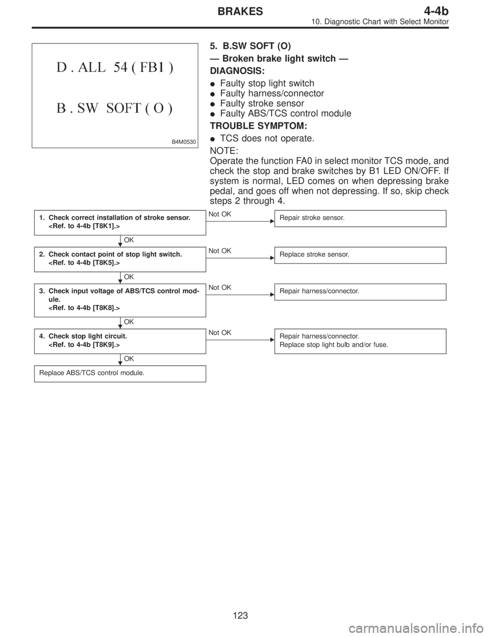
B4M0530
5. B.SW SOFT (O)
—Broken brake light switch—
DIAGNOSIS:
�Faulty stop light switch
�Faulty harness/connector
�Faulty stroke sensor
�Faulty ABS/TCS control module
TROUBLE SYMPTOM:
�TCS does not operate.
NOTE:
Operate the function FA0 in select monitor TCS mode, and
check the stop and brake switches by B1 LED ON/OFF. If
system is normal, LED comes on when depressing brake
pedal, and goes off when not depressing. If so, skip check
steps 2 through 4.
1. Check correct installation of stroke sensor.
OK
�Not OK
Repair stroke sensor.
2. Check contact point of stop light switch.
OK
�Not OK
Replace stroke sensor.
3. Check input voltage of ABS/TCS control mod-
ule.
OK
�Not OK
Repair harness/connector.
4. Check stop light circuit.
OK
�Not OK
Repair harness/connector.
Replace stop light bulb and/or fuse.
Replace ABS/TCS control module.
�
�
�
�
123
4-4bBRAKES
10. Diagnostic Chart with Select Monitor
 Look at the beam angle gauge (vertical movement).
The bubble on the gauge should not deviate from the cen-
ter of the gauge.
B6M0825A
3) Look at the beam angle gauge (horizontal movement).")
 Turn ignition switch to ON.
2) Measure voltage between combination meter connector
and chassis ground.
: Connect")