Page 1148 of 3342
E: INSTALLATION
1) Connect rear housing assembly and strut assembly.
CAUTION:
Use a new self-locking nut.
Tightening torque:
147±15 N⋅m (15±1.5 kg-m, 108±11 ft-lb)
2) Fit BJ (bell joint) to rear housing splines.
CAUTION:
Be careful not to damage inner oil seal lip.
G4M0245
3) Connect rear housing assembly to lateral link assembly.
CAUTION:
Use a new self-locking nut.
Tightening torque:
137±20 N⋅m (14±2 kg-m, 101±14 ft-lb)
G4M0246
4) Connect rear housing assembly to trailing link assem-
bly.
CAUTION:
Use a new self-locking nut.
Tightening torque:
98—127 N⋅m (10—13 kg-m, 72—94 ft-lb)
5) Connect parking brake cable to parking brake.
Disc brake: Perform steps 6) through 8).
6) Install disc rotor on rear housing assembly.
G4M0240
7) Install disc brake caliper on back plate.
Tightening torque:
52±6 N⋅m (5.3±0.6 kg-m, 38.3±4.3 ft-lb)
G4M0266
8) Install rear speed sensor to back plate (only vehicle
equipped with A.B.S.).
22
4-2SERVICE PROCEDURE
2. Rear Axle (AWD Model)
Page 1149 of 3342
 through 11).
9) Clean brake pipe connection. Using a flare-nut wrench,
connect brake pipe to wheel cylinder.
10) Connect parking brake cable to lever.
11) Install brake dr")
Drum brake: Perform steps 9) through 11).
9) Clean brake pipe connection. Using a flare-nut wrench,
connect brake pipe to wheel cylinder.
10) Connect parking brake cable to lever.
11) Install brake drum on rear housing assembly.
12) Bleed air from brake system.
13) Adjust parking brake lever stroke by turning adjuster.
14) Move brake lever back to apply brakes. While
depressing brake pedal, tighten axle nut using a socket
wrench. Lock axle nut after tightening.
Tightening torque:
186±20 N⋅m (19±2 kg-m, 137±14 ft-lb)
CAUTION:
�Use a new axle nut.
�Always tighten axle nut before installing wheel on
vehicle. If wheel is installed and comes in contact with
ground when axle nut is loose, wheel bearings may be
damaged.
�Be sure to tighten axle nut to specified torque. Do
not overtighten it as this may damage wheel bearing.
15) Install wheel and tighten wheel nuts to specified
torque.
Tightening torque:
88±10 N⋅m (9±1 kg-m, 65±7 ft-lb)
3. Rear Axle (FWD Model)
A: REMOVAL
1) Disconnect ground cable from battery.
2) Jack-up vehicle, and remove rear wheel cap and
wheels.
CAUTION:
Be sure to loosen and retighten axle nut after remov-
ing wheel from vehicle. Failure to follow this rule may
damage wheel bearings.
3) Pry hub cap off with a screwdriver placed between it
and hub.
4) Unlock axle nut.
5) Remove axle nut using a socket wrench. Remove
washer.
CAUTION:
Do not re-use old axle nut. Replace with a new one.
NOTE:
Temporarily tighten axle nut to hold hub in place.
23
4-2SERVICE PROCEDURE
2. Rear Axle (AWD Model) - 3. Rear Axle (FWD Model)
Page 1150 of 3342
 through 11).
9) Clean brake pipe connection. Using a flare-nut wrench,
connect brake pipe to wheel cylinder.
10) Connect parking brake cable to lever.
11) Install brake dr")
Drum brake: Perform steps 9) through 11).
9) Clean brake pipe connection. Using a flare-nut wrench,
connect brake pipe to wheel cylinder.
10) Connect parking brake cable to lever.
11) Install brake drum on rear housing assembly.
12) Bleed air from brake system.
13) Adjust parking brake lever stroke by turning adjuster.
14) Move brake lever back to apply brakes. While
depressing brake pedal, tighten axle nut using a socket
wrench. Lock axle nut after tightening.
Tightening torque:
186±20 N⋅m (19±2 kg-m, 137±14 ft-lb)
CAUTION:
�Use a new axle nut.
�Always tighten axle nut before installing wheel on
vehicle. If wheel is installed and comes in contact with
ground when axle nut is loose, wheel bearings may be
damaged.
�Be sure to tighten axle nut to specified torque. Do
not overtighten it as this may damage wheel bearing.
15) Install wheel and tighten wheel nuts to specified
torque.
Tightening torque:
88±10 N⋅m (9±1 kg-m, 65±7 ft-lb)
3. Rear Axle (FWD Model)
A: REMOVAL
1) Disconnect ground cable from battery.
2) Jack-up vehicle, and remove rear wheel cap and
wheels.
CAUTION:
Be sure to loosen and retighten axle nut after remov-
ing wheel from vehicle. Failure to follow this rule may
damage wheel bearings.
3) Pry hub cap off with a screwdriver placed between it
and hub.
4) Unlock axle nut.
5) Remove axle nut using a socket wrench. Remove
washer.
CAUTION:
Do not re-use old axle nut. Replace with a new one.
NOTE:
Temporarily tighten axle nut to hold hub in place.
23
4-2SERVICE PROCEDURE
2. Rear Axle (AWD Model) - 3. Rear Axle (FWD Model)
Page 1153 of 3342
G4M0276
2) Remove back plate from rear spindle.
G4M0277
3) Using ST, press hub bolts out.
CAUTION:
Do not hammer hub bolt since this may deform hub.
ST 927080000 HUB STAND
C: INSPECTION
Clean the removed parts and check them for wear, dam-
age and corrosion. If faulty, replace.
CAUTION:
Hub unit cannot be disassembled. If faulty, replace it
as a unit.
G4M0278
D: ASSEMBLY
1) Using ST, press new hub bolts into place.
NOTE:
�Use a 12 mm (0.47 in) hole in ST to prevent hub bolt
from tilting during installation.
�Ensure hub bolt closely contacts hub.
ST 927080000 HUB STAND
2) Completely clean dust or dirt from the mating/polished
surface of rear spindle back plate.
3) Install back plate to rear spindle.
Tightening torque:
52±6 N⋅m (5.3±0.6 kg-m, 38.3±4.3 ft-lb)
4) Charge oil seal located on the rear of hub with grease.
Specified grease:
SHELL 6459N
26
4-2SERVICE PROCEDURE
3. Rear Axle (FWD Model)
Page 1154 of 3342
 Install hub on rear spindle. Temporarily tighten axle nut
and washer to hold hub in place.
CAUTION:
Discard old axle nut. Replace with a new one.
E: INSTALLATION
1) Connect rear spindle ass")
G4M0275
5) Install hub on rear spindle. Temporarily tighten axle nut
and washer to hold hub in place.
CAUTION:
Discard old axle nut. Replace with a new one.
E: INSTALLATION
1) Connect rear spindle assembly to strut assembly.
Tightening torque:
147±15 N⋅m (15±1.5 kg-m, 108±11 ft-lb)
CAUTION:
Use a new self-locking nut.
G4M0272
2) Connect rear spindle assembly to lateral link assembly.
Tightening torque:
137±20 N⋅m (14±2 kg-m, 101±14 ft-lb)
CAUTION:
Use new self-locking nut.
3) Connect rear spindle assembly to trailing link assembly.
Tightening torque:
113±15 N⋅m (11.5±1.5 kg-m, 83±11 ft-lb)
CAUTION:
Use a new self-locking nut.
Disc brake: Perform steps 4) through 6).
4) Connect end of parking brake cable.
5) Install disc rotor to hub unit.
6) Install disc brake assembly to back plate.
Tightening torque:
52±6 N⋅m (5.3±0.6 kg-m, 38.3±4.3 ft-lb)
Drum brake: Perform steps 7) through 10).
7) Completely clean brake pipe connection. Using a flare-
nut wrench, connect brake pipe to wheel cylinder.
8) Connect parking brake cable to lever.
9) Install brake drum on hub unit.
10) Bleed air from brake system.
11) Tighten axle nut using a socket wrench, and lock
securely.
27
4-2SERVICE PROCEDURE
3. Rear Axle (FWD Model)
Page 1155 of 3342

CAUTION:
�Use a new axle nut.
�Always tighten axle nut before installing wheel on
vehicle. If wheel is installed and comes in contact with")
Tightening torque:
186±20 N⋅m (19±2 kg-m, 137±14 ft-lb)
CAUTION:
�Use a new axle nut.
�Always tighten axle nut before installing wheel on
vehicle. If wheel is installed and comes in contact with
ground when axle nut is loose, wheel bearings may be
damaged.
�Be sure to tighten axle nut to specified torque. Do
not overtighten it as this may damage wheel bearing.
12) Install O-ring to hub cap flange, and install hub cap by
lightly tapping it with a plastic-faced hammer.
13) Install wheel and tighten wheel nuts to specified
torque.
Tightening torque (Wheel nut):
88±10 N⋅m (9±1 kg-m, 65±7 ft-lb)
4. Front and Rear Drive Shafts
A: REMOVAL
1. FRONT DRIVE SHAFT
1) Disconnect ground cable from battery.
2) Jack-up vehicle, support it with safety stands (rigid
racks), and remove front wheel cap and wheels.
3) Unlock axle nut.
4) While depressing brake pedal, remove axle nut using a
socket wrench.
CAUTION:
Be sure to loosen and retighten axle nut after remov-
ing wheel from vehicle. Failure to follow this rule may
damage wheel bearings.
5) Disconnect stabilizer link from transverse link.
6) Disconnect transverse link from housing.
G4M0279
7) Remove spring pin which secures transmission spindle
to DOJ.
CAUTION:
Use a new spring pin.
28
4-2SERVICE PROCEDURE
3. Rear Axle (FWD) - 4. Front and Rear Drive Shafts
Page 1165 of 3342
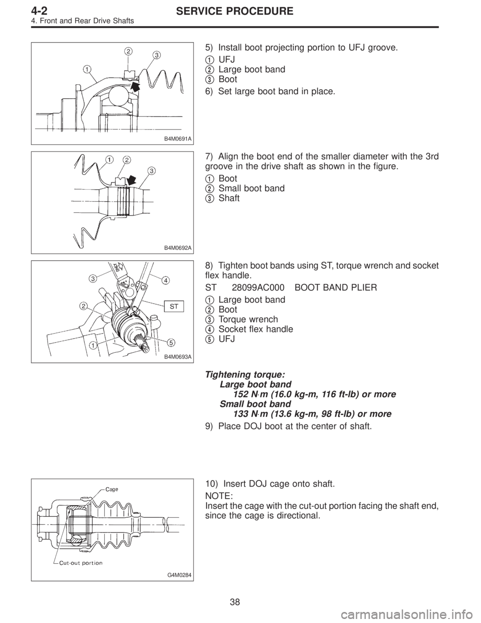
B4M0691A
5) Install boot projecting portion to UFJ groove.
�
1UFJ
�
2Large boot band
�
3Boot
6) Set large boot band in place.
B4M0692A
7) Align the boot end of the smaller diameter with the 3rd
groove in the drive shaft as shown in the figure.
�
1Boot
�
2Small boot band
�
3Shaft
B4M0693A
8) Tighten boot bands using ST, torque wrench and socket
flex handle.
ST 28099AC000 BOOT BAND PLIER
�
1Large boot band
�
2Boot
�
3Torque wrench
�
4Socket flex handle
�
5UFJ
Tightening torque:
Large boot band
152 N⋅m (16.0 kg-m, 116 ft-lb) or more
Small boot band
133 N⋅m (13.6 kg-m, 98 ft-lb) or more
9) Place DOJ boot at the center of shaft.
G4M0284
10) Insert DOJ cage onto shaft.
NOTE:
Insert the cage with the cut-out portion facing the shaft end,
since the cage is directional.
38
4-2SERVICE PROCEDURE
4. Front and Rear Drive Shafts
Page 1171 of 3342
 Connect transverse link to housing.
Tightening torque (self-locking nut):
49±10 N⋅m (5.0±1.0 kg-m, 36±7 ft-lb)
CAUTION:
Use a new self-locking nut.
6) Install stabilizer bracket.
7) While depr")
5) Connect transverse link to housing.
Tightening torque (self-locking nut):
49±10 N⋅m (5.0±1.0 kg-m, 36±7 ft-lb)
CAUTION:
Use a new self-locking nut.
6) Install stabilizer bracket.
7) While depressing brake pedal, tighten axle nut to the
specified torque.
Tightening torque:
186±20 N⋅m (19±2 kg-m, 137±14 ft-lb)
CAUTION:
�Use a new axle nut.
�Always tighten axle nut before installing wheel on
vehicle. If wheel is installed and comes in contact with
ground when axle nut is loose, wheel bearings may be
damaged.
�Be sure to tighten axle nut to specified torque. Do
not overtighten it as this may damage wheel bearing.
8) After tightening axle nut, lock it securely.
G4M0293
2. REAR DRIVE SHAFT
1) Insert BJ into rear housing splines.
CAUTION:
Be careful not to damage inner oil seal lip.
2) Using ST1 and ST2, pull drive shaft into place.
ST1 922431000 AXLE SHAFT INSTALLER
ST2 927390000 ADAPTER
CAUTION:
Do not hammer drive shaft when installing it.
3) Tighten axle nut temporarily.
B4M0549A
4) Using ST, install DOJ into differential.
ST 28099PA090 SIDE OIL SEAL PROTECTOR
B4M0550A
5) Insert DOJ spline end into bore of side oil seal, and
remove ST.
CAUTION:
Do not allow DOJ splines to damage side oil seal.
ST 28099PA090 SIDE OIL SEAL PROTECTOR
44
4-2SERVICE PROCEDURE
4. Front and Rear Drive Shafts
 Connect rear housing assembly and strut assembly.
CAUTION:
Use a new self-locking nut.
Tightening torque:
147±15 N⋅m (15±1.5 kg-m, 108±11 ft-lb)
2) Fit BJ (bell joint) to rear")
 Remove back plate from rear spindle.
G4M0277
3) Using ST, press hub bolts out.
CAUTION:
Do not hammer hub bolt since this may deform hub.
ST 927080000 HUB STAND
C: INSPECTION
Clean the remo")