Page 1737 of 3342
, 100 minutes (AT)
Cold cranking ampere 430 amperes (MT), 490 amperes (AT)
Fuse10 A, 15 A, 20 A
Combination
meterSpeedometer")
1. Body Electrical
A: SPECIFICATIONS
BatteryReserve capacity 82 minutes (MT), 100 minutes (AT)
Cold cranking ampere 430 amperes (MT), 490 amperes (AT)
Fuse10 A, 15 A, 20 A
Combination
meterSpeedometer Electric pulse type
Tachometer Electric impulse type
Water temperature gauge Thermistor cross coil type
Fuel gauge Resistance cross coil type
Charge indicator light 12 V—1.4 W
Brake fluid level warning/parking brake indicator light 12 V—1.4 W
AT oil temperature warning light (AWD only) 12 V—1.4 W
ABS warning light 12 V—1.4 W
CHECK ENGINE warning light
(Malfunction indicator lamp)12 V—1.4 W
Oil pressure warning light 12 V—1.4 W
AIRBAG system warning light 12 V—1.4 W
Low fuel warning light 12 V—3W
FWD indicator light 12 V—1.4 W
TCS warning light 12 V—1.4 W
TCS indicator light 12 V—1.4 W
Turn signal indicator light 12 V—1.4 W (2 pieces)
Seat belt warning light 12 V—1.4 W
Door open warning light 12 V—1.4 W (5 pieces)
Headlight beam indicator light 12 V—1.4 W
Meter illumination light12 V—3 W (2 pieces)
12 V—3.4 W (4 pieces)
Headlight 12 V—60/55 W (Halogen)
Front clearance light 12 V—5W
Turn signal lightFront 12 V—21 W
Rear 12 V—21 W
Tail/Stop light 12 V—5/21 W
Back-up light 12 V—21 W
High-mount stop light12 V—18 W (SEDAN), 12 V—13 W
(WAGON)
License plate light 12 V—5W
Room light 12 V—8W
Trunk room light (SEDAN) 12 V—5W
Luggage room light (WAGON) 12 V—5W
Spot light 12 V—8 W (2 pieces)
Glove box light 12 V—3.4 W
Ash tray illumination light 12 V—1.7 W
Selector lever illumination light (AT model) 12 V—1.7 W
2
6-2SPECIFICATIONS
1. Body Electrical
Page 1776 of 3342
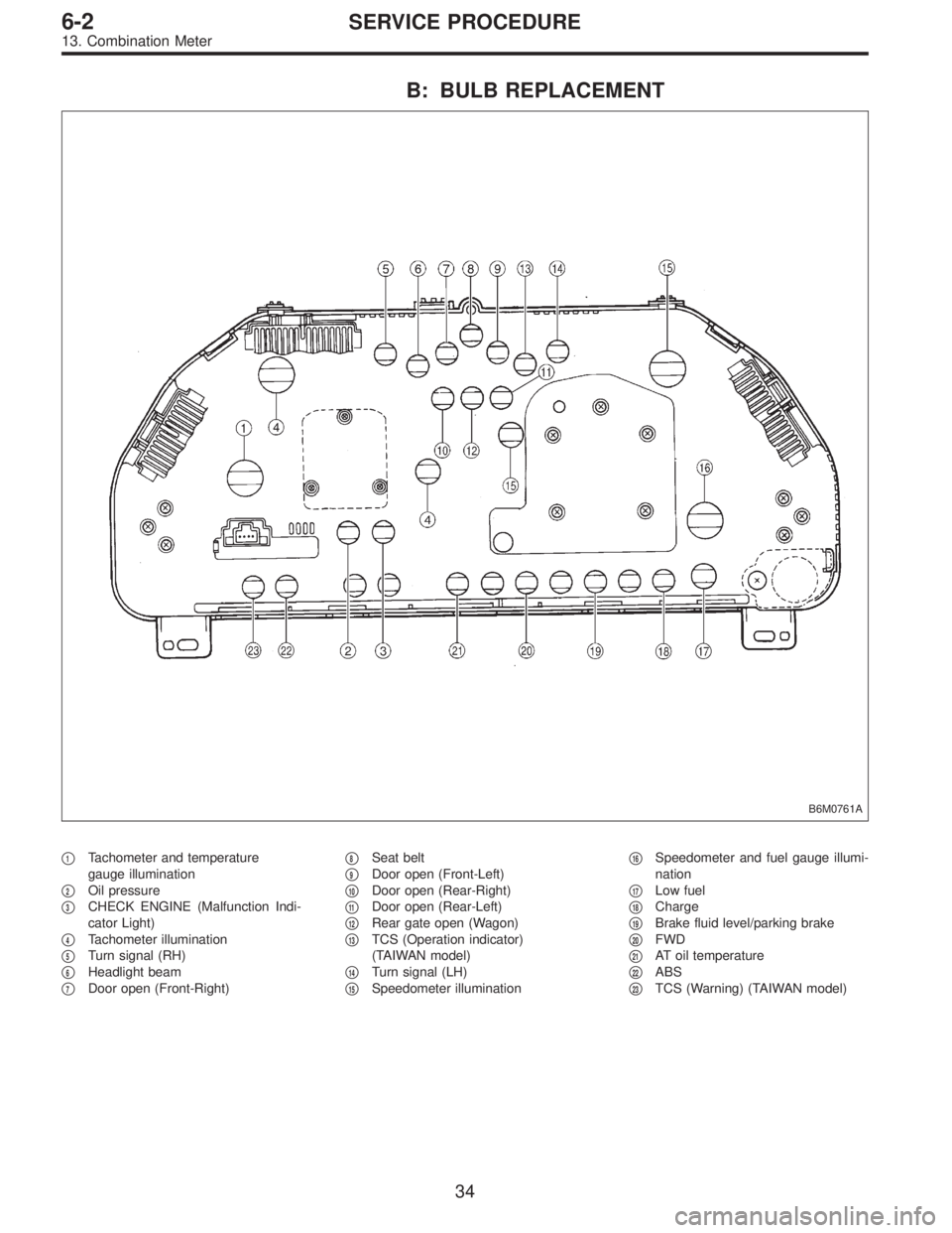
B: BULB REPLACEMENT
B6M0761A
�1Tachometer and temperature
gauge illumination
�
2Oil pressure
�
3CHECK ENGINE (Malfunction Indi-
cator Light)
�
4Tachometer illumination
�
5Turn signal (RH)
�
6Headlight beam
�
7Door open (Front-Right)�
8Seat belt
�
9Door open (Front-Left)
�
10Door open (Rear-Right)
�
11Door open (Rear-Left)
�
12Rear gate open (Wagon)
�
13TCS (Operation indicator)
(TAIWAN model)
�
14Turn signal (LH)
�
15Speedometer illumination�
16Speedometer and fuel gauge illumi-
nation
�
17Low fuel
�
18Charge
�
19Brake fluid level/parking brake
�
20FWD
�
21AT oil temperature
�
22ABS
�
23TCS (Warning) (TAIWAN model)
34
6-2SERVICE PROCEDURE
13. Combination Meter
Page 1856 of 3342

�
2Ignition coil
�
3Ignitor
�
4Crankshaft position sensor
�
5Camshaft position sensor
�
6Throttle position sensor
�
7Fuel injectors
�
8Pressure regulator
�
9Engine coolan")
�1Engine control module (ECM)
�
2Ignition coil
�
3Ignitor
�
4Crankshaft position sensor
�
5Camshaft position sensor
�
6Throttle position sensor
�
7Fuel injectors
�
8Pressure regulator
�
9Engine coolant temperature sensor
�
10Mass air flow sensor
�
11Idle air control solenoid valve
�
12Purge control solenoid valve
�
13Fuel pump
�
14PCV valve
�
15Air cleaner
�
16Canister
�
17Main relay
�
18Fuel pump relay
�
19Fuel filter
�
20Front catalytic converter
�
21Rear catalytic converter
�
22EGR valve (AT vehicles only)
�
23EGR control solenoid valve (AT vehicles only)
�
24Radiator fan�
25Radiator fan relay
�
26Pressure sources switching solenoid valve
�
27Knock sensor
�
28Back-pressure transducer (AT vehicles only)
�
29Front oxygen sensor
�
30Rear oxygen sensor (2200 cc Federal spec. vehicles)
�
31Pressure sensor
�
32A/C compressor
�
33Inhibitor switch
�
34CHECK ENGINE malfunction indicator lamp (MIL)
�
35Tachometer
�
36A/C relay
�
37A/C control module
�
38Ignition switch
�
39Transmission control module (TCM) (AT vehicles only)
�
40ABS/TCS control module (TCS equipped models)
�
41Vehicle speed sensor
�
42Data link connector (For Subaru select monitor)
�
43Data link connector (For Subaru select monitor and OBD-II
general scan tool)
�
44Two way valve
�
45Rear oxygen sensor (2200 cc California spec. vehicles)
�
46Filter
5
2-7ON-BOARD DIAGNOSTICS II SYSTEM
1. General
Page 1884 of 3342

Refers to data denoting the current operating condition of
analog input/output, digital input/output and/or the power-
train system.
A list of the supp")
3. CURRENT POWERTRAIN DIAGNOSTIC DATA
(MODE $01)
Refers to data denoting the current operating condition of
analog input/output, digital input/output and/or the power-
train system.
A list of the support data and PID (Parameter Identification)
codes are shown in the following table.
PID DataUnit of measure
01 Number of emission-related powertrain trouble codes and MIL status ON/OFF
03 Fuel system control status—
04 Calculated engine load value%
05 Engine coolant temperature°C
06 Short term fuel trim%
07 Long term fuel trim%
0B Intake manifold absolute pressurekPa
0C Engine revolutionrpm
0D Vehicle speedkm/h
0E Ignition timing advance°
10 Air flow rate from mass air flow sensor g/sec
11 Throttle valve opening angle%
13 Check whether oxygen sensor is installed.—
14 Oxygen sensor output voltage and short term fuel trim associated with oxygen sensor—bank 1 V and %
15 Oxygen sensor output voltage and short term fuel trim associated with oxygen sensor—bank 2 V and %
1C On-board diagnosis system—
NOTE:
Refer to OBD-II general scan tool manufacturer’s instruc-
tion manual to access generic OBD-II PIDs (MODE $01).
33
2-7ON-BOARD DIAGNOSTICS II SYSTEM
3. Diagnosis System
Page 1885 of 3342

Refers to data denoting the operating condition when
trouble is sensed by the on-board diagnosis system.
A list of the support data and PID (Parameter Identi")
4. POWERTRAIN FREEZE FRAME DATA (MODE $02)
Refers to data denoting the operating condition when
trouble is sensed by the on-board diagnosis system.
A list of the support data and PID (Parameter Identification)
codes are shown in the following table.
PID DataUnit of measure
02 Trouble code that caused CARB required freeze frame data storage—
03 Fuel system control status—
04 Calculated engine load value%
05 Engine coolant temperature°C
06 Short term fuel trim%
07 Long term fuel trim%
0B Intake manifold absolute pressurekPa
0C Engine revolutionrpm
0D Vehicle speedkm/h
NOTE:
Refer to OBD-II general scan tool manufacturer’s instruc-
tion manual to access freeze frame data (MODE $02).
5. EMISSION-RELATED POWERTRAIN DIAGNOSTIC
TROUBLE CODE (MODE $03)
Refers to data denoting emission-related powertrain diag-
nostic trouble codes.
For details concerning diagnostic trouble codes, refer to
the DIAGNOSTIC TROUBLE CODE (DTC) LIST.
2-7 [T10A0], [T11A0].>
NOTE:
Refer to OBD-II general scan tool manufacturer’s instruc-
tion manual to access emission-related powertrain diag-
nostic trouble codes (MODE $03).
34
2-7ON-BOARD DIAGNOSTICS II SYSTEM
3. Diagnosis System
Page 1893 of 3342

6. READ DATA FUNCTION KEY LIST FOR ENGINE
Function mode Contents Abbreviation Unit of measure
F00 ROM ID number YEAR—
F01 Battery voltage VB V
F02 Vehicle speed signal VSP km/h, MPH
F03 Engine speed signal EREV rpm
F04 Engine coolant temperature signal TW°C,°F
F05 Ignition signal ADVS deg
F06 Mass air flow signal QA g/s, V
F07 Throttle position signal THV %, V
F08 Injector pulse width TIM mS
F09 Idle air control signal ISC %
F10 Load data LOAD %
F11 Front oxygen sensor output signal O2 V
F12 Front oxygen sensor maximum and minimum output signal O2max - min V, V
F13 Rear oxygen sensor output signal RO2 V
F14 Rear oxygen sensor maximum and minimum output signal RO2max - min V, V
F17 Short term fuel trim ALPHA %
F19 Knock sensor signal KNOCK deg
F20 Atmospheric absolute pressure signal BARO. P kPa, mmHg
F21 Intake manifold absolute pressure signal MANI. P kPa, mmHg
F29A/F correction coefficient [short term trim] by rear oxygen sen-
sorPHOS %
F30 Long term fuel trim [A/F learning correction coefficient] KBLRC %
F31 Long term fuel trim whole [A/F learning control coefficient] K0 %
F32 Front oxygen sensor heater current FO2H A
F33 Rear oxygen sensor heater current RO2H A
F35 Purge control solenoid valve duty ratio CPCD %
F36Maximum value of cylinder #1 misfire times during 100 rota-
tionsMF1 %
F37Maximum value of cylinder #2 misfire times during 100 rota-
tionsMF2 %
F38Maximum value of cylinder #3 misfire times during 100 rota-
tionsMF3 %
F39Maximum value of cylinder #4 misfire times during 100 rota-
tionsMF4 %
F42Maximum and minimum EGR system pressure value (AT
vehicles)EGRmax - min kPa
F43 Fuel tank pressure signal TNKP kPa, mmHg
F44 Fuel temperature signal TNKT°C,°F
F45 Fuel level signal FLEVEL V
FA 0 O N)OFF signal——
FA 1 O N)OFF signal——
FA 2 O N)OFF signal——
FA 3 O N)OFF signal——
FA 4 O N)OFF signal——
FA 5 O N)OFF signal——
FB0 Diagnostic trouble code (DTC) INSPECT—
FB1 Diagnostic trouble code (DTC) OBD—
42
2-7ON-BOARD DIAGNOSTICS II SYSTEM
3. Diagnosis System
Page 1894 of 3342
 LOAD�F %
Engine coolant temperature signal (Freeze frame data) TW�F °C
Short term fuel trim (Freeze frame data) AL")
Function mode Contents Abbreviation Unit of measure
FB2Load data (Freeze frame data) LOAD�F %
Engine coolant temperature signal (Freeze frame data) TW�F °C
Short term fuel trim (Freeze frame data) ALPH�F %
Long term fuel trim (Freeze frame data) KBLR�F %
Intake manifold absolute pressure signal (Freeze frame data) MANI�F kPa
Engine speed signal (Freeze frame data) EREV�F rpm
Vehicle speed signal (Freeze frame data) VSP�F km/h
FB3Mass air flow signal (Freeze frame data) QA�F (P0100) V
Pressure signal (Freeze frame data) PS�F (P0105) V
Pressure signal (Freeze frame data) PR�F (P0106) V
Engine coolant temperature signal (Freeze frame data) TW�F (P0115) V
Throttle position signal (Freeze frame data) THV�F (P0120) V
EGR control solenoid valve signal (Freeze frame data) EGR (P0403) —*1
Purge control solenoid valve signal (Freeze frame data) CPC (P0443) —*1
Start switch signal (Freeze frame data) STSW (P1100) —*1
Pressure sources switching solenoid valve signal (Freeze
frame data)BR1 (P1102) —*1
Radiator fan relay 1 signal (Freeze frame data) FAN1 (P1500) —*1
FC0 Clear memory — —
FD01 Compulsory fuel pump relay operation check FUEL PUMP —
FD02 Compulsory purge control solenoid valve operation check CPC SOL —
FD03 Compulsory radiator fan relay operation check RAD FAN —
FD04 Compulsory A/C relay operation check A/C RELAY —
FD05 Compulsory EGR control solenoid valve operation check EGR SOL —
FD07 Compulsory pressure control solenoid valve operation check PCV SOL —
FD08 Compulsory vent control solenoid valve operation check VENT SOL —
FD10Compulsory pressure sources switching solenoid valve opera-
tion checkBR SOL —
NOTE:
�Subaru select monitor is also available for monitoring
information other than that used for check and repair of the
vehicle.
�F42 (Maximum and minimum EGR system pressure
value) will not read accurately until the EGR flow diagno-
sis terminates.
EGR flow diagnosis terminates when LED No. 2 illuminates
at function mode FA4.
�*1: “Hi” or “Low” is shown instead of measured value.
�Because ASV solenoid valve, FICD solenoid valve and
air injection system diagnosis solenoid valve are not
installed, FD06, FD09 and FD11 will be displayed but non-
functional.
43
2-7ON-BOARD DIAGNOSTICS II SYSTEM
3. Diagnosis System
Page 1899 of 3342
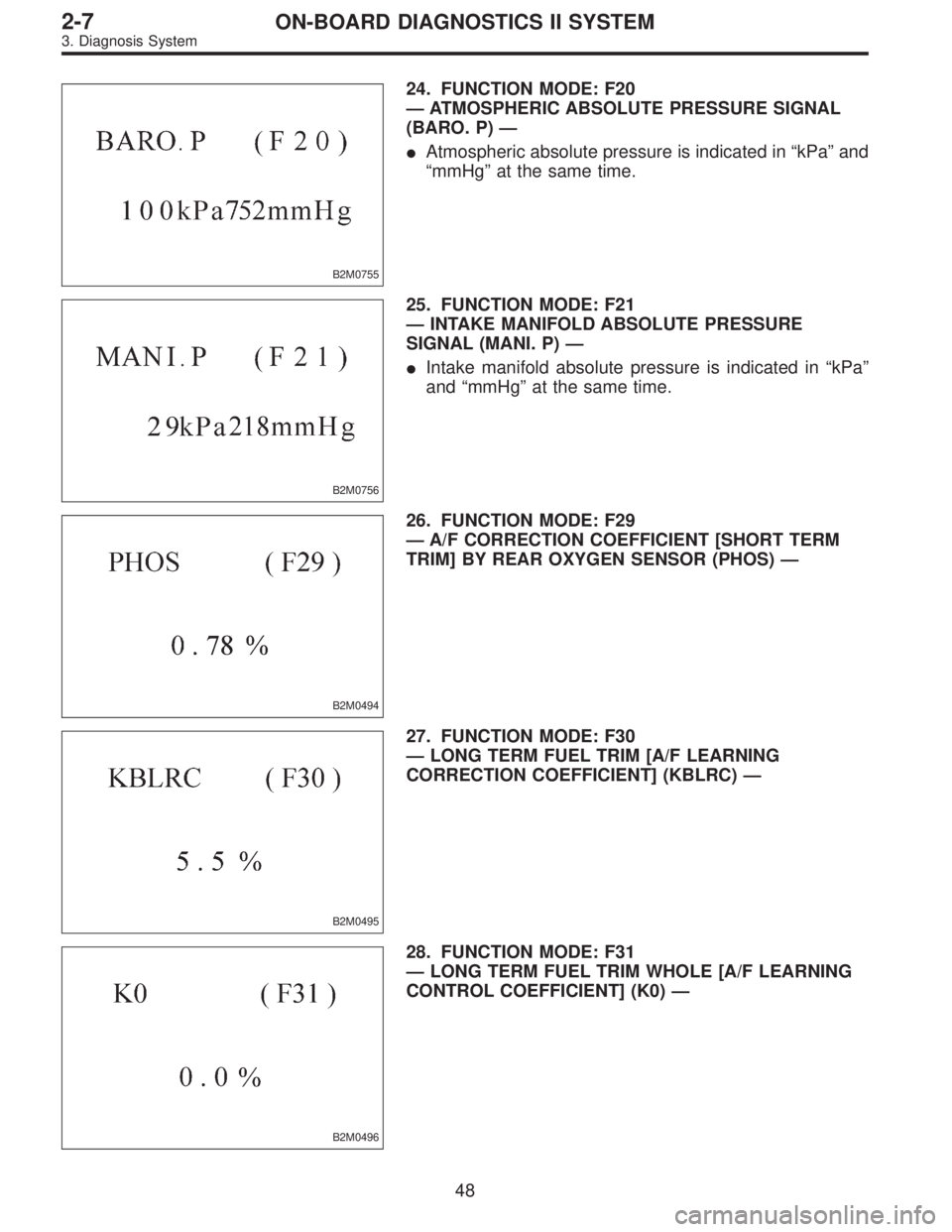
B2M0755
24. FUNCTION MODE: F20
—ATMOSPHERIC ABSOLUTE PRESSURE SIGNAL
(BARO. P)—
�Atmospheric absolute pressure is indicated in“kPa”and
“mmHg”at the same time.
B2M0756
25. FUNCTION MODE: F21
—INTAKE MANIFOLD ABSOLUTE PRESSURE
SIGNAL (MANI. P)—
�Intake manifold absolute pressure is indicated in“kPa”
and“mmHg”at the same time.
B2M0494
26. FUNCTION MODE: F29
—A/F CORRECTION COEFFICIENT [SHORT TERM
TRIM] BY REAR OXYGEN SENSOR (PHOS)—
B2M0495
27. FUNCTION MODE: F30
—LONG TERM FUEL TRIM [A/F LEARNING
CORRECTION COEFFICIENT] (KBLRC)—
B2M0496
28. FUNCTION MODE: F31
—LONG TERM FUEL TRIM WHOLE [A/F LEARNING
CONTROL COEFFICIENT] (K0)—
48
2-7ON-BOARD DIAGNOSTICS II SYSTEM
3. Diagnosis System