Page 2450 of 3342
 Connect connectors to TCM and transmission.
2) Lift-up or raise the vehicle and place safety stands.
CAUTION:
On AWD models, raise all wheels off floor.
3) P")
OBD0396A
3. CHECK INPUT SIGNAL FOR TCM.
1) Connect connectors to TCM and transmission.
2) Lift-up or raise the vehicle and place safety stands.
CAUTION:
On AWD models, raise all wheels off floor.
3) Push the TCS OFF switch to ON. (With TCS models)
4) Start the engine and set vehicle in 20 km/h (12 MPH)
condition.
5) Measure voltage between TCM connector terminals.
Connector & terminal / Specified voltage:
(B54) No. 12—No. 7 / AC 1 V, or more
NOTE:
The speed difference between front and rear wheels may
light either the ABS or the ABS/TCS warning light, but this
indicates no malfunctions. When AT control diagnosis is
finished, perform the ABS or the ABS/TCS memory clear-
ance procedure of self-diagnosis system.
or 4-4d [T6D2] or [T9J0].>
OBD0145A
B3M0413
OBD0399
�Using Subaru select monitor:
(1) Connect connectors to TCM and transmission.
(2) Turn ignition switch to OFF.
(3) Connect the Subaru select monitor to data link con-
nector.
(4) Lift-up or raise the vehicle and place safety stands.
CAUTION:
On AWD models, raise all wheels off floor.
(5) Turn ignition switch to ON and Subaru select moni-
tor switch to ON.
(6) Push the TCS OFF switch to ON. (With TCS mod-
els)
(7) Start the engine and operate at constant speed.
(8) Read data on Subaru select monitor.
(9) Designate mode using function key.
Function mode: F02 or F03
SPECIFIED DATA:
F02: Compare speedometer with monitor indica-
tions.
F03: Compare speedometer with monitor indica-
tions.
�F02: Vehicle speed is indicated in“m/h”.
�F03: Vehicle speed is indicated in“km/h”.
NOTE:
The speed difference between front and rear wheels may
light either the ABS or the ABS/TCS warning light, but this
indicates no malfunctions. When AT control diagnosis is
finished, perform the ABS or the ABS/TCS memory clear-
ance procedure of self-diagnosis system.
or 4-4d [T6D2] or [T9J0].>
46
3-2AUTOMATIC TRANSMISSION AND DIFFERENTIAL
7. Diagnostic Chart with Trouble Code
Page 2451 of 3342
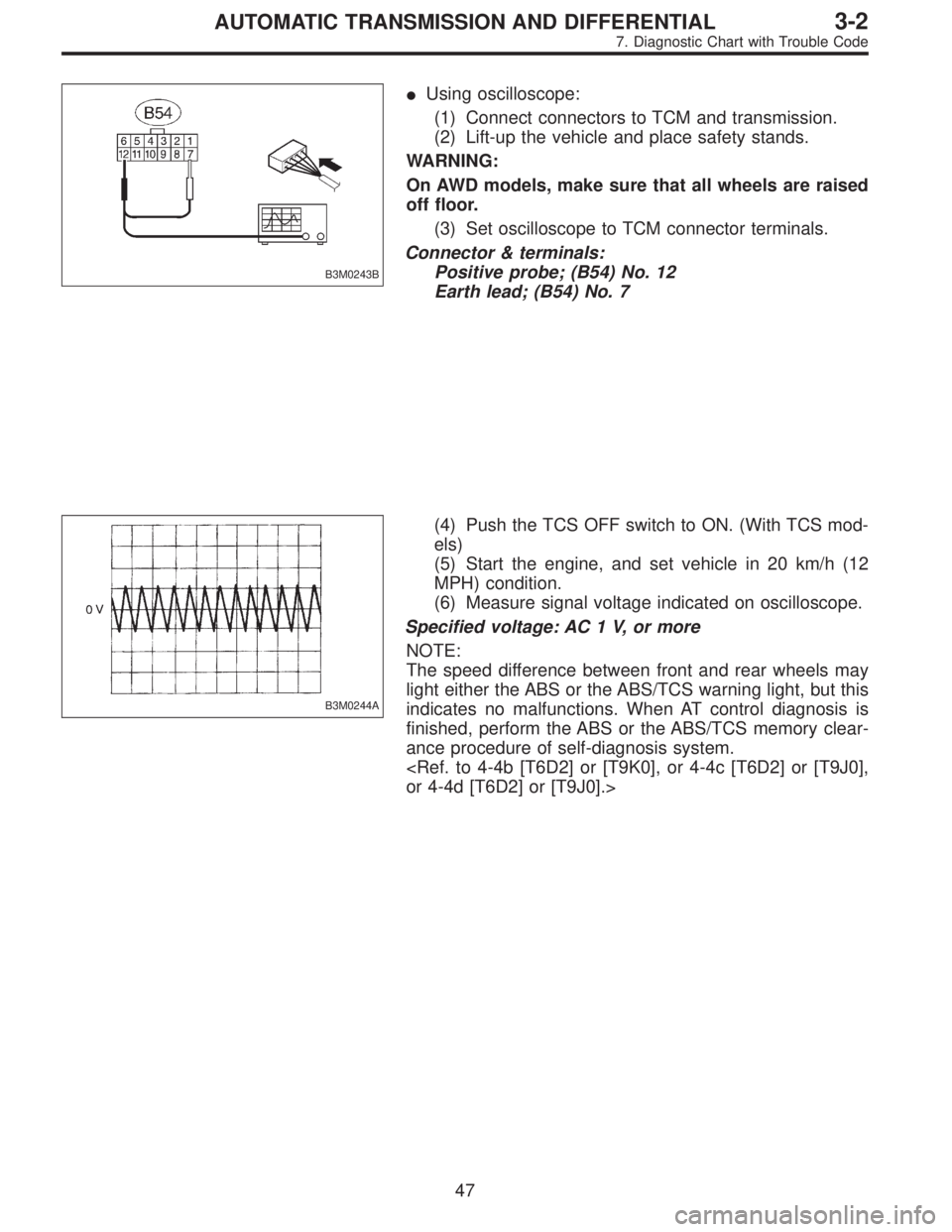
B3M0243B
�Using oscilloscope:
(1) Connect connectors to TCM and transmission.
(2) Lift-up the vehicle and place safety stands.
WARNING:
On AWD models, make sure that all wheels are raised
off floor.
(3) Set oscilloscope to TCM connector terminals.
Connector & terminals:
Positive probe; (B54) No. 12
Earth lead; (B54) No. 7
B3M0244A
(4) Push the TCS OFF switch to ON. (With TCS mod-
els)
(5) Start the engine, and set vehicle in 20 km/h (12
MPH) condition.
(6) Measure signal voltage indicated on oscilloscope.
Specified voltage: AC 1 V, or more
NOTE:
The speed difference between front and rear wheels may
light either the ABS or the ABS/TCS warning light, but this
indicates no malfunctions. When AT control diagnosis is
finished, perform the ABS or the ABS/TCS memory clear-
ance procedure of self-diagnosis system.
or 4-4d [T6D2] or [T9J0].>
47
3-2AUTOMATIC TRANSMISSION AND DIFFERENTIAL
7. Diagnostic Chart with Trouble Code
Page 2454 of 3342
 Install combination meter.
2) Connect connector to TCM.
3) Lift-up the vehicle and place safety stand.
CAUTION:
On AWD models, raise all wheels off floor.
4")
B3M0289
3. CHECK VEHICLE SPEED SENSOR 2.
1) Install combination meter.
2) Connect connector to TCM.
3) Lift-up the vehicle and place safety stand.
CAUTION:
On AWD models, raise all wheels off floor.
4) Disconnect connector from vehicle speed sensor 2.
5) Measure resistance between terminals of vehicle speed
sensor 2.
Terminals / Specified resistance:
(B17) No. 1—No. 2 / 350—450Ω
No. 1—Body/1MΩ, or more
No. 2—Body/1MΩ, or more
B3M0256
6) Push the TCS OFF switch to ON. (With TCS models)
7) Start the engine and set vehicle in 20 km/h (12 MPH)
condition.
8) Measure output signal of vehicle speed sensor 2.
WARNING:
Be careful not to be caught up by the running wheels.
9) Using a voltage meter; measure voltage between termi-
nals of vehicle speed sensor 2.
Terminals / Specified voltage:
(B17) No. 1—No. 2 / AC 2 V, or more
NOTE:
The speed difference between front and rear wheels may
light either the ABS or the ABS/TCS warning light, but this
indicates no malfunctions. When AT control diagnosis is
finished, perform the ABS or the ABS/TCS memory clear-
ance procedure of self-diagnosis system.
or 4-4d [T6D2] or [T9J0].>
50
3-2AUTOMATIC TRANSMISSION AND DIFFERENTIAL
7. Diagnostic Chart with Trouble Code
Page 2455 of 3342
 Install combination meter.
(2) Connect connector to TCM.
(3) Lift-up the vehicle and place safety stand.
WARNING:
On AWD models, make sure that all wheels are raised
o")
B3M0257
�Using oscilloscope:
(1) Install combination meter.
(2) Connect connector to TCM.
(3) Lift-up the vehicle and place safety stand.
WARNING:
On AWD models, make sure that all wheels are raised
off floor.
(4) Set oscilloscope to vehicle speed sensor 2.
Connector & terminal / No. 1—No. 2
B3M0254A
(5) Push the TCS OFF switch to ON. (With TCS mod-
els)
(6) Start the engine, and drive the wheels slowly.
(7) Measure signal voltage indicated on oscilloscope.
Specified voltage: AC 2 V, or more
NOTE:
The speed difference between front and rear wheels may
light either the ABS or the ABS/TCS warning light, but this
indicates no malfunctions. When AT control diagnosis is
finished, perform the ABS or the ABS/TCS memory clear-
ance procedure of self-diagnosis system.
or 4-4d [T6D2] or [T9J0].>
B3M0369A
4. CHECK INPUT SIGNAL FOR TCM.
1) Connect connector to vehicle speed sensor 2.
2) Lift-up the vehicle or set the vehicle on free roller.
CAUTION:
On AWD models, raise all wheels off floor.
3) Push the TCS OFF switch to ON. (With TCS models)
4) Start the engine, and drive the wheels slowly.
5) Measure voltage between TCM and body.
Connector & terminal / Specified voltage:
(B56) No. 11—Body / Less than 1↔
more than 9 V
NOTE:
The speed difference between front and rear wheels may
light either the ABS or the ABS/TCS warning light, but this
indicates no malfunctions. When AT control diagnosis is
finished, perform the ABS or the ABS/TCS memory clear-
ance procedure of self-diagnosis system.
or 4-4d [T6D2] or [T9J0].>
51
3-2AUTOMATIC TRANSMISSION AND DIFFERENTIAL
7. Diagnostic Chart with Trouble Code
Page 2456 of 3342
 Install combination meter.
(2) Connect connectors to TCM and vehicle speed
sensor 2.
(3) Lift-up the vehicle or set the vehicle on free roller.
(4) Turn igni")
OBD0145A
�Using Subaru select monitor:
(1) Install combination meter.
(2) Connect connectors to TCM and vehicle speed
sensor 2.
(3) Lift-up the vehicle or set the vehicle on free roller.
(4) Turn ignition switch to OFF.
(5) Connect the Subaru select monitor to data link con-
nector.
(6) Turn ignition switch to ON and Subaru select moni-
tor switch to ON.
CAUTION:
On AWD models, raise all wheels off floor.
(7) Push the TCS OFF switch to ON. (With TCS mod-
els)
G3M0726
B3M0384
(8) Start the engine, and drive the wheels.
(9) Read data on Subaru select monitor.
(10) Designate mode using function key.
Function mode: F04 or F05
SPECIFIED DATA:
Compare speedometer with select monitor indica-
tions.
�F04: Vehicle speed is indicated in mile per hour (MPH).
�F05: Vehicle speed is indicated in kilometer per hour
(km/h).
NOTE:
The speed difference between front and rear wheels may
light either the ABS or the ABS/TCS warning light, but this
indicates no malfunctions. When AT control diagnosis is
finished, perform the ABS or the ABS/TCS memory clear-
ance procedure of self-diagnosis system.
or 4-4d [T6D2] or [T9J0].>
B3M0248B
�Using oscilloscope:
(1) Connect connector to vehicle speed sensor 2.
(2) Lift-up the vehicle or set the vehicle on free rollers.
CAUTION:
On AWD models, raise all wheels off floor.
(3) Set oscilloscope to TCM connector terminals.
Connector & terminals:
Positive probe; (B56) No. 11
Earth lead; Body
52
3-2AUTOMATIC TRANSMISSION AND DIFFERENTIAL
7. Diagnostic Chart with Trouble Code
Page 2457 of 3342
G2M0931
(4) Push the TCS OFF switch to ON. (with TCS mod-
els)
(5) Start the engine.
(6) Shift on the gear position, and keep the vehicle
speed at constant.
(7) Measure signal voltage.
Specified voltage: 2 V, or more
NOTE:
If vehicle speed increases, the width of amplitude (W)
decreases.
NOTE:
The speed difference between front and rear wheels may
light either the ABS or the ABS/TCS warning light, but this
indicates no malfunctions. When AT control diagnosis is
finished, perform the ABS or the ABS/TCS memory clear-
ance procedure of self-diagnosis system.
or 4-4d [T6D2] or [T9J0].>
53
3-2AUTOMATIC TRANSMISSION AND DIFFERENTIAL
7. Diagnostic Chart with Trouble Code
Page 2460 of 3342

2. ON←→OFF SIGNAL LIST
Mode LED No. Signal name Display LED“ON”requirements Page
FA 01 FWD switch FF When fuse is installed in FWD switch.—
2 Kick-down switch KD—
3—— —
4—— —
5 Brake switch BR When brake switch is turned ON.—
6 ABS switch AB When ABS signal is entered.—
7 Cruise control set CR When cruise control is set.—
8 Power switch PW—
9—— —
10—— —
FA 11 P/N range switch NP When P or N range is selected.—
2 R range switch RR When R range is selected.—
3 D range switch RD When D range is selected.—
4 3 range switch R3 When 3 range is selected.—
5 2 range switch R2 When 2 range is selected.—
6 1 range switch R1 When 1 range is selected.—
7 Diagnosis switch SS When diagnosis switch is turned ON. 66
8—— —
9—— —
10—— —
NOTE; LED Nos. 2 and 8 cannot be turned on.
3. DIAGNOSIS MODE
Mode Contents Abbr. Contents of display
FB0On-board
diagnosticsDIAG.U Current trouble code determined by on-board diagnostics.
FB1On-board
diagnosticsDIAG.MPrevious trouble code stored in memory by on-board
diagnostics.
FC0 Back-up clear—Function of clearing trouble code stored in memory.
56
3-2AUTOMATIC TRANSMISSION AND DIFFERENTIAL
8. Diagnostic Chart with Select Monitor
Page 2467 of 3342
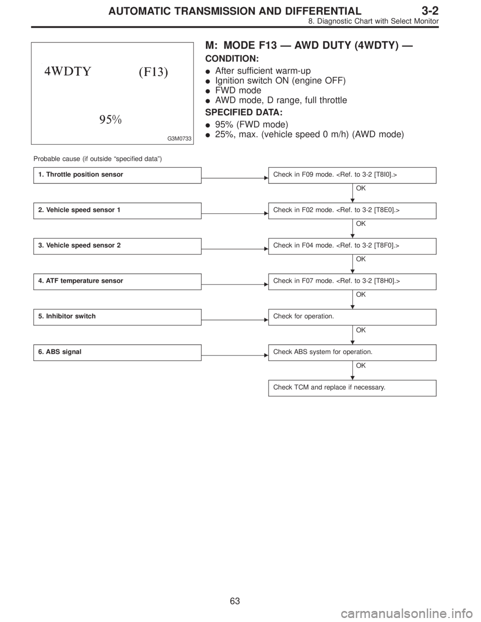
G3M0733
M: MODE F13—AWD DUTY (4WDTY)—
CONDITION:
�After sufficient warm-up
�Ignition switch ON (engine OFF)
�FWD mode
�AWD mode, D range, full throttle
SPECIFIED DATA:
�95% (FWD mode)
�25%, max. (vehicle speed 0 m/h) (AWD mode)
Probable cause (if outside“specified data”)
1. Throttle position sensor
�Check in F09 mode.
OK
2. Vehicle speed sensor 1
�Check in F02 mode.
OK
3. Vehicle speed sensor 2
�Check in F04 mode.
OK
4. ATF temperature sensor
�Check in F07 mode.
OK
5. Inhibitor switch
�Check for operation.
OK
6. ABS signal
�Check ABS system for operation.
OK
Check TCM and replace if necessary.
�
�
�
�
�
�
63
3-2AUTOMATIC TRANSMISSION AND DIFFERENTIAL
8. Diagnostic Chart with Select Monitor
 Push the TCS OFF switch to ON. (with TCS mod-
els)
(5) Start the engine.
(6) Shift on the gear position, and keep the vehicle
speed at constant.
(7) Measure signal voltage.
Specified volta")